JOHNSON CONTROLS
22
SECTION 5 – LEVELING THE UNIT
FORM 155.17-N1
ISSUE DATE: 4/1/2013
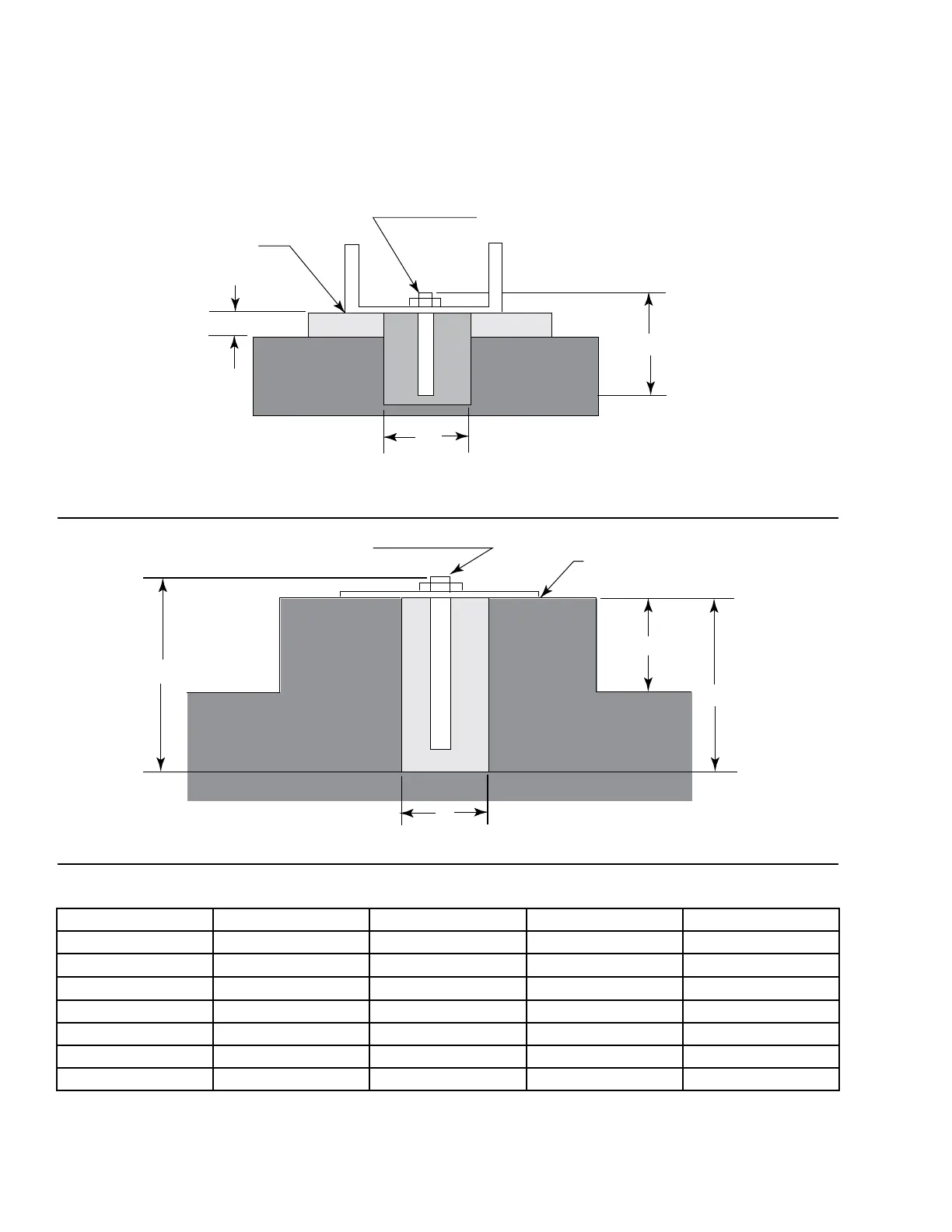
ANCHORING
Since there is little vibration, anchor bolts are not nec-
essary in most locations. However, in areas known to
experience tremors, bolting down the unit is recom-
mended. Fasten the legs to the foundation with anchor
bolts after leveling the unit. See Figure 4 on page 21.
BOTTOM
OF UNIT
ANCHOR BOLT
4"
12-3/8"
FLOOR
MIN. 4"
FIGURE 6 - S-MODEL UNITS
ld05300
ANCHOR BOLT
BOTTOM OF UNIT
B
C
FLOOR
A
D
FIGURE 7 - G-MODEL UNITS
ld05301
TABLE 1 - ANCHORING DIAGRAM DIMENSIONS
UNIT A B C D
18G 19-1/2" 5" (minimum) 19-1/2" 4"
19G 19-1/2" 5" (minimum) 19-1/2" 4"
19GL 19-1/2" 5" (minimum) 19-1/2" 6"
20G 19-1/2" 5" (minimum) 19-1/2" 6"
21G 19-1/2" 5" (minimum) 19-1/2" 4"
22G 19" 5" (minimum) 19" 6"
22GL 19" 5" (minimum) 19" 6"
 Loading...


