JOHNSON CONTROLS
90
APPENDIX A - TABLES
FORM 155.17-N1
ISSUE DATE: 4/1/2013
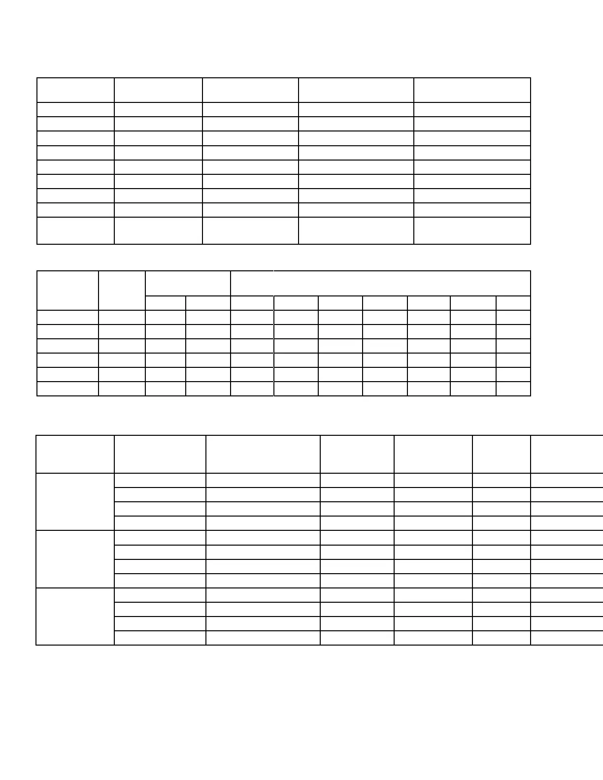
TABLE 10 - OIL PUMP SUCTION CAPACITY AND FILTER SELECTION CHART FOR POWER FLAME
BURNERS
YORK MODEL
UNIT
BURNER MODEL
SUCTION CAPACITY
(GPH)
POWER FLAME OIL FIL-
TER MODEL
ALTERNATE OIL FILTER
12SC / 13S CR2-G(O)-20 40 70101-100 73410 (Fulo FB-6)
13SC / 14S CR3-G(O)-20 105 70101-100 73410 (Fulo FB-6)
14SC / 15S CR3-G(O)-25 105 70101-100 73420 (Fulo FB-10)
15SL CR4-G(O)-25 135 70101-100 73420 (Fulo FB-10)
16S CR4-G(O)-25 135 70101-100 73420 (Fulo FB-10)
16SL CR4-G(O)-25 135 70101-100 73420 (Fulo FB-10)
17S CR4-G(O)-25 135 70101-100 73420 (Fulo FB-10)
18S CR4-G(O)-30 135 70101-100 73420 (Fulo FB-10)
19S CR5-G(O)-30 250 70101-100
“73290 (#72 1" Hayward
w/100 mesh basket)”
TABLE 11 - COMBUSTION AIR REQUIREMENTS FOR POWER FLAME BURNERS
BURNER
MODEL
RATED
MBH
COMBUSTION
AIR REQUIRED
APPROXIMATE FLUE GAS FLOW RATES AT VARYING STACK TEM-
PERATURE (ACFM)
LB/HR SCFM 77°F 250°F 300°F 350°F 400°F 450°F 500°F
cr2-G(o)-20B 3,080 2,653 590 621 821 879 937 994 1,052 1,110
CR3-G(O)-20 3,650 3,144 699 736 973 1,041 1,110 1,178 1,247 1,315
CR3-G(O)-25 4,718 4,064 903 951 1,258 1,346 1,435 1,523 1,612 1,700
CR4-G(O)-25 6,300 5,427 1,206 1,270 1,679 1,797 1,916 2,034 2,152 2,270
CR4-G(O)-30 7,840 6,753 1,501 1,580 2,090 2,237 2,384 2,531 2,678 2,825
CR5-G(O)-30 10,500 9,044 2,010 2,117 2,799 2,996 3,193 3,390 3,587 3,784
Based on 20% excess air (dry) at 77°F
TABLE 13 - ELECTRICAL DATA - STEAM FIRED UNITS
CHILLER
MODEL
VOLTAGE MAX DUAL ELEMENT
FUSE
(CUSTOMER SUPPLIED)
TOTAL UNIT
AMPACITY
MINIMUM CIR-
CUIT
AMPACITY
SOLUTION
PUMP FLA
REFRIGERANT PUMP
FLA
PURGE PUMP
FLA
SOLUTION SPRAY
PUMP #1 FLA
SOLUTION SPRAY
PUMP #2 FLA
MICRO & POWER
PANELS FLA
14SC 200/208-3-60 60 34.9 40.4 22.0 6.2 1.7 N/A N/A 5.0
230-3-60 50 31.4 36.4 20.0 5.6 1.5 N/A N/A 4.3
380-3-50 30 17.2 19.9 11.0 3.1 0.9 N/A N/A 2.6
460-3-60 25 16.2 18.7 10.0 2.8 0.8 N/A N/A 2.2
16SL, 17S & 18S 200/208-3-60 125 74.3 84.5 40.6 13.8 1.7 13.2 N/A 5.0
230-3-60 110 66.6 75.8 36.8 12.0 1.5 12.0 N/A 4.3
380-3-50 60 36.5 41.3 19.0 7.0 0.9 7.0 N/A 2.6
460-3-60 50 33.4 38.0 18.4 6.0 0.8 6.0 N/A 2.2
19S 200/208-3-60 125 94.2 104.4 40.6 13.8 1.7 33.1 N/A 5.0
230-3-60 125 84.6 93.8 36.8 12.0 1.5 30.0 N/A 4.3
380-3-50 70 46.5 51.3 19.0 7.0 0.9 17.0 N/A 2.6
460-3-60 60 42.4 47.0 18.4 6.0 0.8 15.0 N/A 2.2
NOTES:
1. Electrical system must be securely grounded.
2. Direct-Fired table is based on a Power Flame burner.
3. Field wiring must conform to N.E.C. and all other applicable local codes.
4. Incoming wire to chiller must be copper only. Aluminum wiring is not permitted.
5. Connection lugs in power panel will accept incoming wire range of #14 AWG through #1/0 AWG for 380 volt and 460 volt chillers. For 200,
208 and 230 volt chillers, lugs will accept #4 to 350 MCM wire.
 Loading...


