JOHNSON CONTROLS
40
SECTION 12 – BURNER INSTALLATION (POWER FLAME BURNERS)
FORM 155.17-N1
ISSUE DATE: 4/1/2013
unit in spec tion. If it has, disregard this step and contin-
ue. Components that were not mount ed on the burn er
(ship loose) are des ig nat ed with an “L” on the sheets.
Claims of dam age to the burn er or shortage must be
im me di ate ly filed with the carrier. Support the burn er
with the Power Flame sup plied pedestal. Cut the ship-
ping tie-wraps from the U-bolt af ter the burn er is well
supported by the pedestal.
The following pages show the typical arrangements
and components of the burner and gas trains. Gas units
will have similar components, however, all oil compo-
nents shown will not be present. For specifics on your
system, refer to the technical information supplied with
the burner.
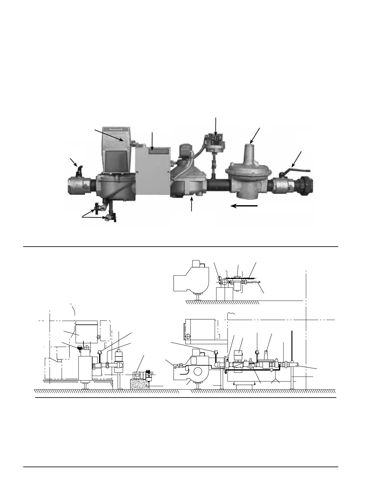
FIGURE 13 - TYPICAL GAS TRAIN COMPONENTS
00268VIP
Main Manual
Gas Shut-off
Cock
Main Gas
Pressure
Regulator
Low Gas Pressure
Switch
Redundant Main
Gas Solenoid
Valve
Gas Train Junc-
tion Box
Main Gas Valve
w/ Proof of Clo-
sure Switch
Manual Gas Check-
ing Cock
Gas Valve Leak
Test Valves
Flow Direction
FIGURE 14 - TYPICAL BURNER ASSEMBLY FOR DIRECT-FIRED, S-MODEL UNITS
LD05307
ITEM NAME
01 Base (For Oil Pump Unit)
02 Support (For Oil Pump)
03 Gas Supply Piping
04 Oil Supply Piping
05 Oil Return Piping
06 Union
07 Main Gas Shut-O Cock
ITEM NAME
08 Main Gas Pressure Regulator
09 Low Gas Pressure Switch
10 Auxiliary Gas Valve
11 Pilot Regulator
12 Main Gas Shut-O Valve
13 Manual Leak Test Shut-O Valve
14 Gas Pressure Gauge
ITEM NAME
15 High Gas Pressure Switch
16 Manual Gas Shut-O Valve
17 Oil Pump Unit
18 Oil Filter
19 Oil Compound Gauge
20 Burner Unit
21 Burner Control Panel
SHELL CENTER LINE
SHELL CENTER LINE
SHELL CENTER LINE
SHELL CENTER LINE
NOTE: SOME OF THE EQUIPMENT LISTED
MAY NOT BE APPLICABLE TO ALL INSTALLATIONS
OIL RETURN
OIL SUPPLY
16 6
10
YORK
YORK
YORK
19
18
5
4
21
11
15
17
6
1
15
14
20
2
13
12
9
8
6
 Loading...


