JOHNSON CONTROLS
65
21
FORM 155.17-N1
ISSUE DATE: 4/1/2013
SECTION 21 – BAROMETRIC DAMPERS
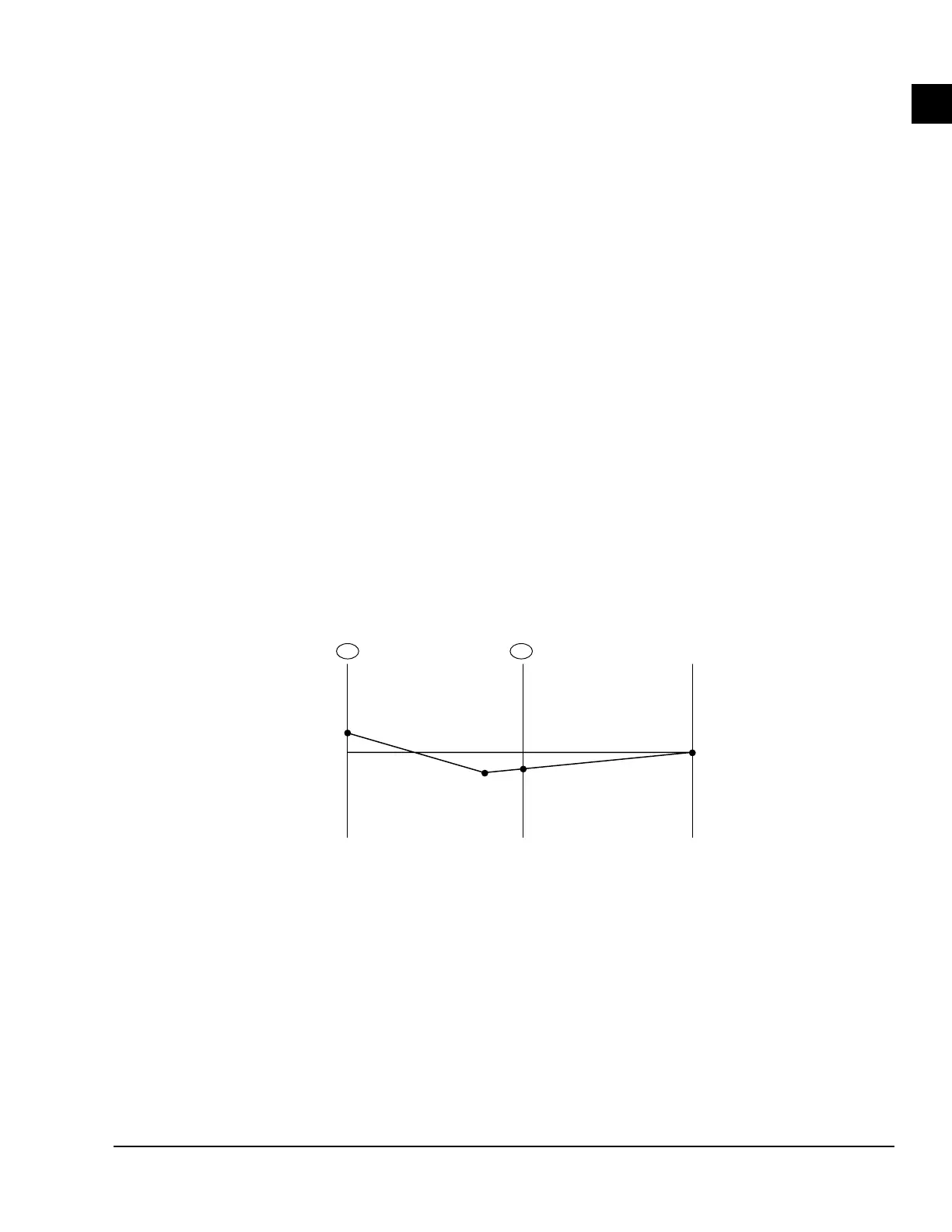
The Barometric Control Figure and Graph de pict a
sim ple yet effective means of con trol ling draft with
maximum econ o my employed in the chimney design.
With this sys tem, a baro met ric draft reg u la tor (field
sup plied) is used in se ries with a manual backdraft
damp er (fac to ry sup plied – see previous pages). A
baro met ric damp er is suit able for ap pli ca tions where
each gas-fired appliance will have its own ded i cat ed
chim ney.
Johnson Controls will not be re spon si ble for costs
as so ci at ed with ret ro fit ting damp ers to im prop er-
ly de signed chim neys. With max i mum econ o my em-
ployed in the chim ney de sign, Dt would exactly equal
dP - Da (eq. 2) dur ing sum mer de sign am bi ent con-
di tions with the baro met ric reg u la tor closed. In real-
ity, some degree of con ser va tism should exist in the
design, causing the baro met ric draft reg u la tor to be
open slight ly even dur ing summer design con di tions.
As am bi ent tem per a tures drop, (Dt) would in crease.
If not for the baro met ric draft regulator in place, me-
chanical room air is introduced into the chim ney as
in response to the in creased draft, thus stabilizing the
gauge pressure just upstream of the baro met ric reg u-
la tor. Most barometric regulators can main tain -0.06
inch es water gauge pres sure when properly sized for a
particular ap pli ca tion.
With the gauge pressure thus stabilized just upstream
of the barometric regulator, the manual backdraft
damper can be adjusted to a fixed position which will
provide the proper resistance or pressure drop to yield
a sufficient steady burner flame.
A
B
C
D
TOP OF
CHIMNEY
PRESSURE
GAUGE STUB
CHILLER-HEATER
OUTLET
1 2
GAUGE
PRESSURE
(IN. WATER)
0
+
–
Point B is at base of
Vertical section
FIGURE 30 - GAUGE PRESSURE PROFILE / CHIMNEY SYSTEM WITH BAROMETRIC CONTROL
LD05356
NOTES:
1. dP between A and B due to transition piece and properly positioned manual backdraft damper. Damper adjusted to maintain water at A.
2. Maximum draft (minimum gauge pressure) occurs at base of vertical section of chimney (B). Barometric regulator will maintain steady
gauge pressure at (C). Maximum gauge pressure attainable with a barometric draft regulator is typically -0.06 in. water.
 Loading...


