– 105 –
②
2-Pedal unit
1
)
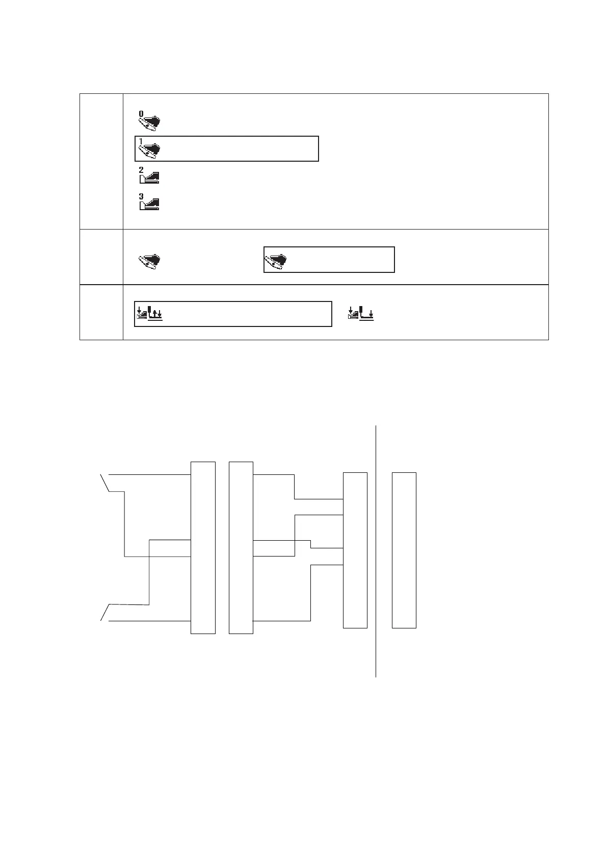
Set the memory switches as follows.
Select the framed items.
U019 Selection of pedal
: Standard pedal
: Standard pedal (2-step stroke)
: Option pedal
: Option pedal (2-step stroke)
U020 Selection of Start pedal
: Standard pedal
: Option pedal
U024 Optional pedal 1 operation
: OFF when depressing pedal again
: OFF when detaching pedal
The right-side switch controls the presser foot and the left-side switch controls the start of the sewing
machine.
2
)
Wiring diagram
1
2
3
4
5
6
7
8
9
10
1
2
3
4
5
6
7
8
9
10
1
2
3
4
5
6
7
8
9
1
2
3
4
5
6
7
8
9
+5V
PRSR
GND
+5V
START
GND
+5V
PRSL
GND
CN41
M85205800A0
Left switch
Right switch
M90125900A0
MAIN PWB

 Loading...