03.09 EN
40
• Test the warning signal button (6).
• Test the deadman button (27, 28) and controller (13).
The truck is now operational. The steering is set straight-ahead.
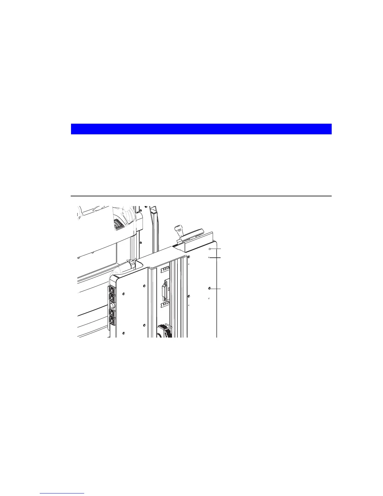
3.3 Individual assembly of the second control station control panels
The left and right-hand control panels of the second control station (O) can be set to
two different heights "A" or "B".
Assembling the control panel for the second control station
NOTE
Improper assembly of the control panel can cause material damage.
XWhen removing the control panel make sure no wires or plug connectors are
trapped or disconnected.
XPrevent the control panel from falling down.
XWhen installing the control panel make sure no wires or plug connectors are
trapped or disconnected.
Procedure
• Undo the four mounting screws (29) on each control panel, while preventing the
control panel from falling down.
• Pull out the control panel approx. 60 mm in the drive direction.
• Install the control panel again with the required height "A" or "B".
• Fix the control panel again with the four mounting screws (29).
• Ensure the mounting screws (29) are tight.
• Test the controls on the control panel are working correctly.
The control panel is now assembled.
A
B
29
03.09 EN
40
• Test the warning signal button (6).
• Test the deadman button (27, 28) and controller (13).
The truck is now operational. The steering is set straight-ahead.
3.3 Individual assembly of the second control station control panels
The left and right-hand control panels of the second control station (O) can be set to
two different heights "A" or "B".
Assembling the control panel for the second control station
NOTE
Improper assembly of the control panel can cause material damage.
XWhen removing the control panel make sure no wires or plug connectors are
trapped or disconnected.
XPrevent the control panel from falling down.
XWhen installing the control panel make sure no wires or plug connectors are
trapped or disconnected.
Procedure
• Undo the four mounting screws (29) on each control panel, while preventing the
control panel from falling down.
• Pull out the control panel approx. 60 mm in the drive direction.
• Install the control panel again with the required height "A" or "B".
• Fix the control panel again with the four mounting screws (29).
• Ensure the mounting screws (29) are tight.
• Test the controls on the control panel are working correctly.
The control panel is now assembled.
A
B
29
 Loading...