reference [REF] or negative potential terminal for Contact 1 of the corresponding alarm and provides a
current path for external alarm devices. Table 11 on page 55 describes the functions of the alarm contacts.
Table 11: Alarm Relay Contact Functions
FunctionContact NameContact Name
Current is not flowing through Contact 1 and Contact 2 [REF] when
operating normally. When the current flows, the closed alarm is
generated.
Normally Open (NO)Contact 1
Current is flowing through Contact 1 and Contact 2 [REF] when
operating normally. When the current stops flowing, the open alarm
is generated.
Normally Closed (NC)
Provides the current path for the external alarm-reporting device
and functions as a reference or negative potential terminal for
Contact 1.
Reference (REF)Contact 2
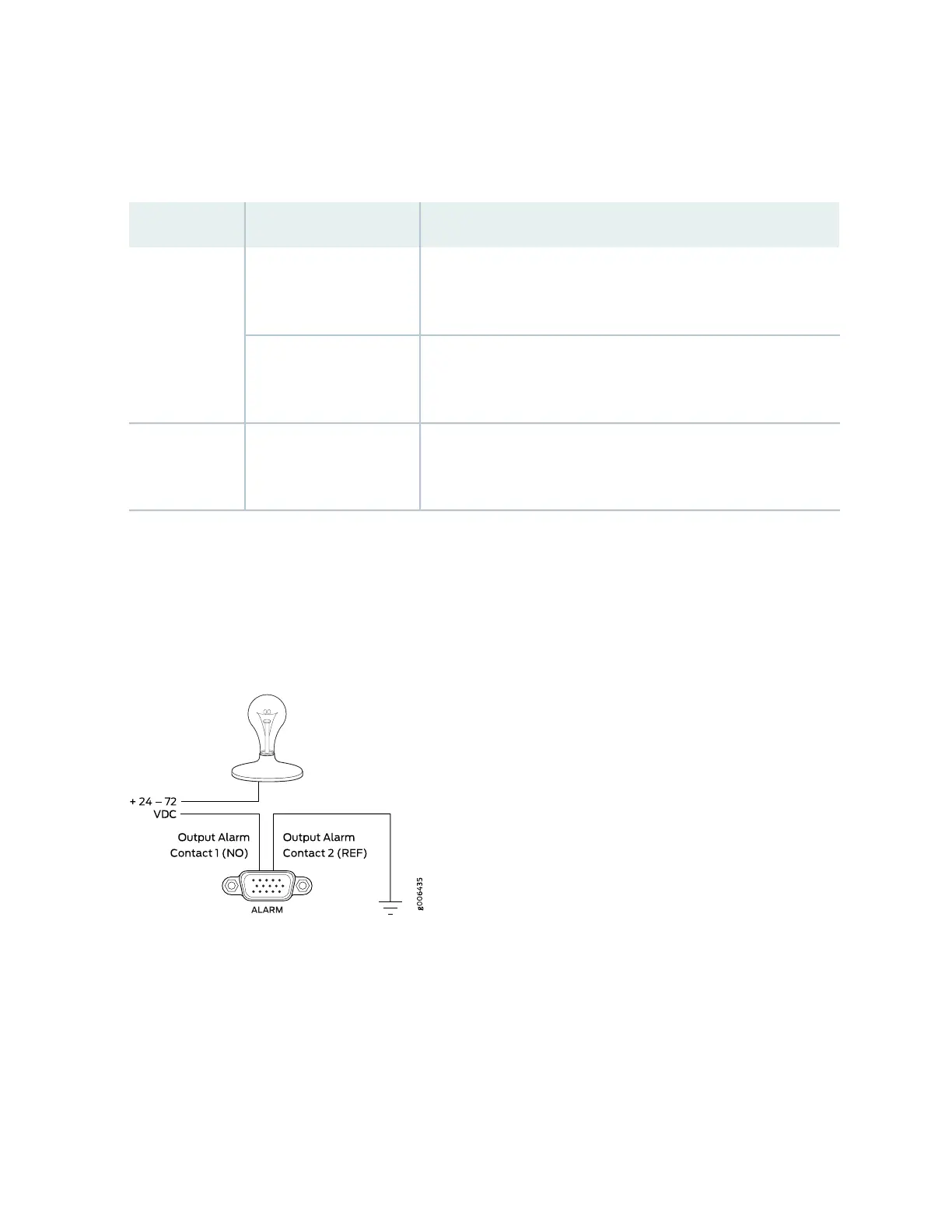
Figure 12 on page 55 shows an example of a wiring diagram for a simple output alarm-reporting device.
In this case the device is a light bulb that illuminates when the device encounters a condition that activates
the red alarm LED and relay contacts. The alarm relay contacts can also be used to activate other devices
such as bells or buzzers.
Figure 12: Sample Output Alarm-Reporting Device
Figure 13 on page 56 shows an example of a wiring diagram for a simple input alarm-reporting device. In
this case the push button switch is an alarm sensor that triggers an input alarm when a door-open condition
occurs.
55