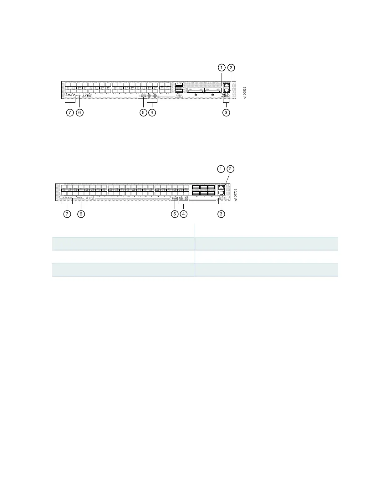
Figure 17: Management Panel Components on ACX5448-D
Figure 18 on page 31 shows the management panel components on ACX5448-M routers.
Figure 18: Management Panel Components on ACX5448-M
5—1— USB portManagement (MGMT) port
6—2— RESET buttonConsole (CON) port
7—3— Status LEDsLINK and ST LEDs
4—PPS and 10M GPS output ports
The management panel consists of the following components:
•
Status LEDs—ALM, SYS, MST, and ID LEDs
•
Router product number
•
Management (MGMT) port— RJ-45 connectors for 10/100/1000BASE-T. See “Connect an ACX5400
Router to a Network for Out-of-Band Management” on page 107.
•
Console (CON) port— RJ-45 connector to support RS-232 serial ports.
•
Link activity (left LED labeled LINK) and port status (right LED labeled ST) LEDs.
•
USB port for image updates.
•
Reset button to reset the device.
•
Two SMB connector ports that support 1-PPS and 10-MHz timing devices.
31