•
Two 100-Gigabit Ethernet ports (36 and 37, mapped to CLI PIC 1) that support QSFP28 transceivers.
You can channelize these ports into four 25-Gbps interfaces using breakout cables (and channelization
configuration). These ports also support 40-Gbps speed, when you use QSFP+ optics. You can channelize
these 40-Gbps ports into four 10-Gbps interfaces using breakout cables (and channelization configuration).
•
Two 200-Gigabit Ethernet ports (38 and 39, mapped to logical PIC 2) that support 200-gigabit CFP2-DCO
transceivers.
NOTE: One QSFP28 port (port 36) and one CFP2-DCO port (port 38) can operate as multiplexer
ports.
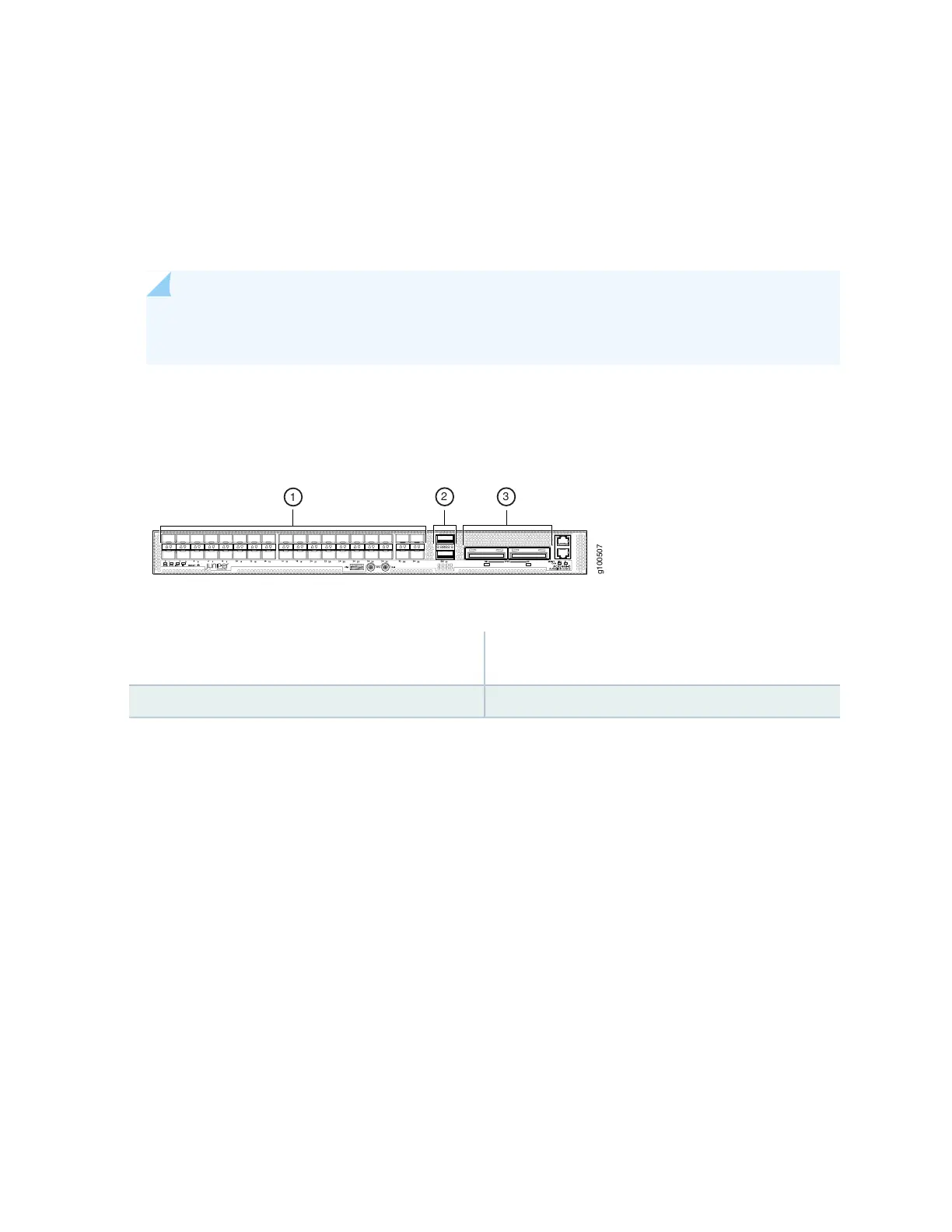
Figure 20 on page 33 shows the port panel of an ACX5448-D router.
Figure 20: ACX5448-D Router Port Panel
3—1— 100–Gigabit/200-Gigabit Ethernet ports (2
CFP2-DCO ports)
1- Gigabit/10–Gigabit Ethernet ports (36 SFP+ ports)
2—100–Gigabit Ethernet ports (2 QSFP28 ports)
Port, Interface, and PIC Mapping
The ACX5448-D does not have a physical FPC or PIC. FPC 0 refers to the router. The ports on the front
panel are mapped to logical PICs as follows:
•
Ports 0–35 mapped to PIC 0 (interfaces xe-0/0/0 through xe-/0/0/35)
•
Ports 36 and 37 mapped to PIC 1 (interfaces et-0/1/0 and et-0/1/1)
•
Ports 38 and 39 mapped to PIC 2 (interfaces ot-0/2/0 and ot-0/2/1)
For each CFP2-DCO optical module installed in ports 38 and 39, one optical transport (ot-) interface is
created. Therefore, the ACX5448-D supports two ot- interfaces—ot-0/2/0 and ot-0/2/1. You can map
two 100-Gigabit Ethernet (et-) interfaces to each ot- interface, depending on the configured rate—100
Gbps or 200 Gbps—for the CFP2-DCO module. As a result, four et- interfaces are possible—et-0/2/0,
et-0/2/1, et-0/2/2, and et-0/2/3.
33