•
1 RJ-45 console port
•
1 USB port
•
1-Gigabit management port
•
4 system status LEDs
•
3 port parameter LEDs
•
1 Mode button
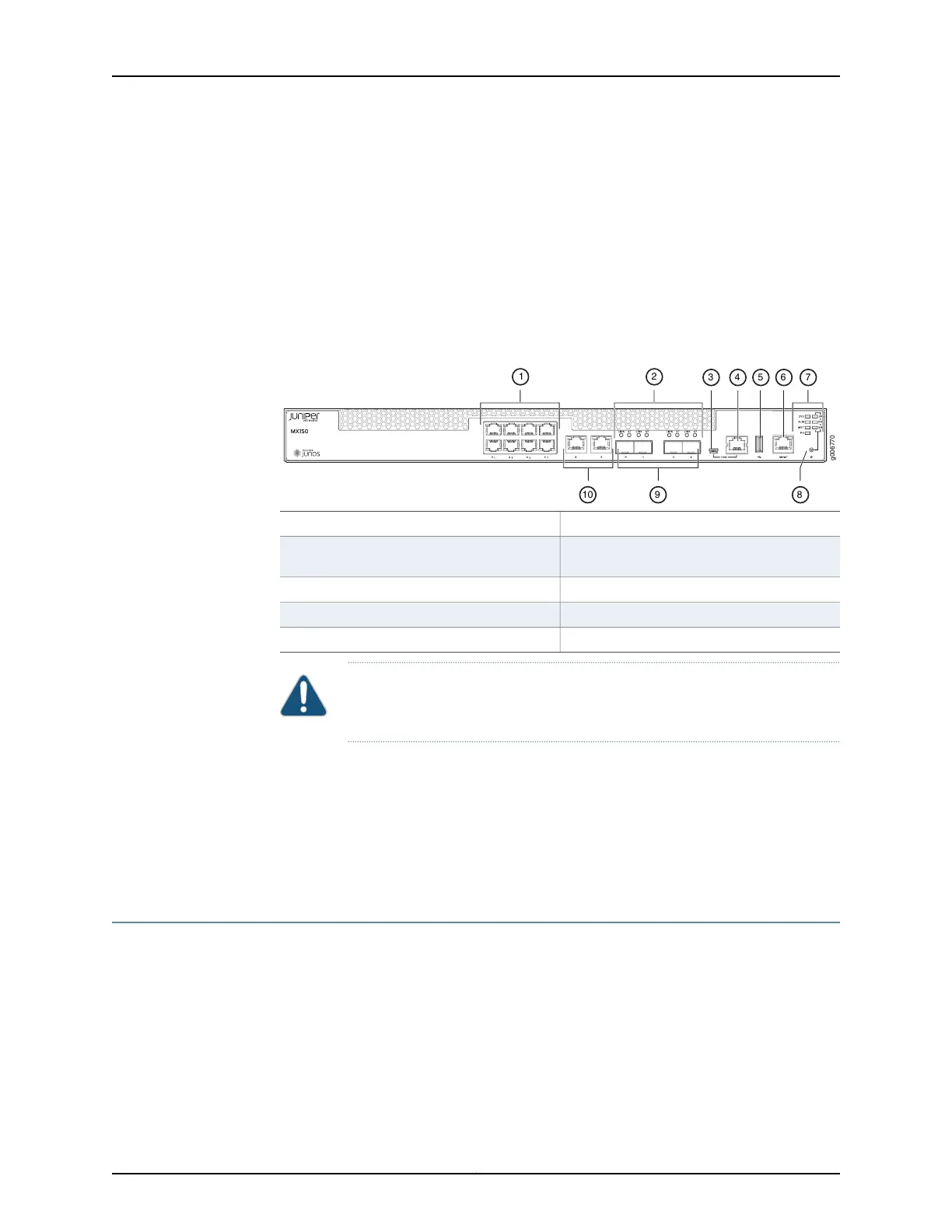
Figure 2: MX150 Front Panel Components
6—1— 1-Gigabit management (mgmt) port1-Gigabit Ethernet RJ-45 network ports
7—2— system status LEDs and port parameter
LEDs
Link and Status LEDs for SFP and SFP+
ports
8—3— Mode buttonMini-USB console port
9—4— 1/10-Gigabit SFP+ uplink portsConsole (CON) port
10—5— 1-Gigabit SFP network or uplink portsUSB port
CAUTION: Do not use the Reset button to restart the power sequence unless
under the direction of Juniper Networks Technical Assistance Center (JTAC).
Related
Documentation
Chassis Status LEDs on MX150 on page 7•
• Cooling System and Airflow in an MX150 on page 13
• Prevention of Electrostatic Discharge Damage on page 151
• Connecting an MX150 to a Network for Out-of-Band Management on page 89
Rear Panel of an MX150
The rear panel of the MX150 consists of the following components (see
Figure 3 on page 7):
•
Ground area
•
Electrostatic discharge (ESD) point
•
Exhaust vents
Copyright © 2017, Juniper Networks, Inc.6
MX150 3D Universal Edge Router Hardware Guide