as provided in Table 25 on page 69 (here, the link is 2 km long and multimode, and
the (P
B
) is 13 dBm):
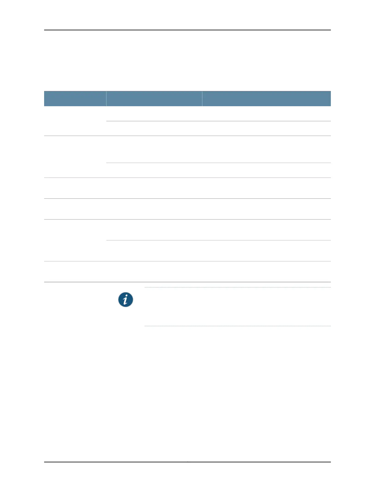
Table 25: Estimated Values for Factors Causing Link Loss
Sample Link Loss (LL) Calculation ValuesEstimated Link-Loss ValueLink-Loss Factor
0.5 dBmMultimode—0.5 dBmHigher-ordermodelosses
0 dBmSingle-mode—None
0 dBmMultimode—None, if product of
bandwidth and distance is less
than 500 MHz/km
Modal and chromatic
dispersion
0 dBmSingle-mode—None
This example assumes five connectors. Loss for five
connectors: 5 (0.5 dBm) = 2.5 dBm.
0.5 dBmConnector
This example assumes two splices. Loss for two splices:
2 (0.5 dBm) = 1 dBm.
0.5 dBmSplice
This example assumes the link is 2 km long. Fiber
attenuation for 2 km: 2 km (1 dBm/km) = 2 dBm.
Multimode—1 dBm/kmFiber attenuation
This example assumes the link is 2 km long. Fiber
attenuation for 2 km: 2 km (0.5 dBm/km) = 1 dBm.
Single-mode—0.5 dBm/km
1 dBm1 dBmClock Recovery Module
(CRM)
NOTE: For information about the actual amount of signal loss caused by
equipment and other factors, see your vendor documentation for that
equipment.
2. Calculate the (P
M
) by subtracting (LL) from (P
B
):
P
B
– LL = P
M
13 dBm – 0.5 dBm [HOL] – 5 (0.5 dBm) – 2 (0.5 dBm) – 2 km (1.0 dBm/km) – 1 dB
[CRM] = P
M
13 dBm – 0.5 dBm – 2.5 dBm – 1 dBm – 2 dBm – 1 dBm = P
M
P
M
= 6 dBm
The calculated power margin is greater than zero, indicating that the link has sufficient
power for transmission. Also, the power margin value does not exceed the maximum
receiver input power. Refer to the specifications for your receiver to find the maximum
receiver input power.
69Copyright © 2017, Juniper Networks, Inc.
Chapter 8: Transceiver and Cable Specifications