•
Power switch
•
AC power cord inlet
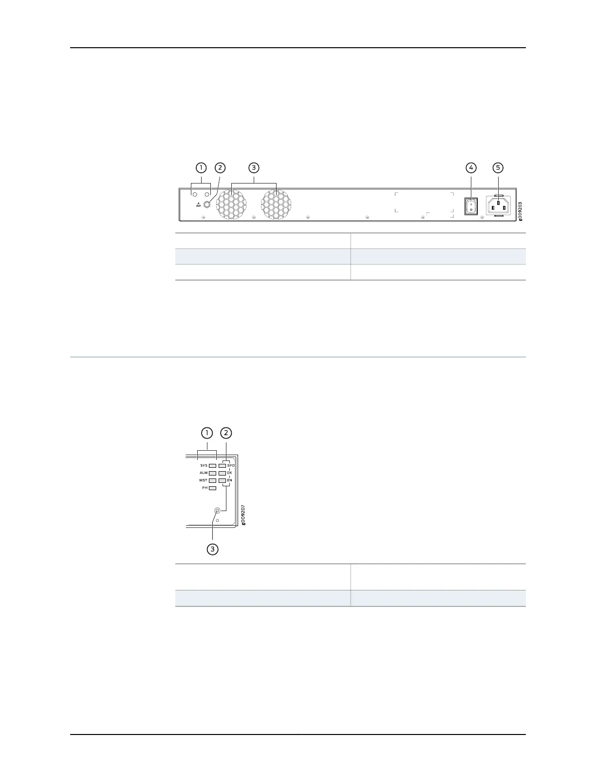
Figure 3: MX150 Rear Panel
4—1— Power switchGround area
5—2— AC power cord inletElectrostatic discharge (ESD) point
3—Exhaust vents
Related
Documentation
Front Panel of an MX150 on page 5•
• Cooling System and Airflow in an MX150 on page 13
Chassis Status LEDs on MX150
The front panel of an MX150 has chassis status LEDs (labeled ALM, SYS, MST and PH),
next to the MGMT port (see Figure 4 on page 7).
Figure 4: Chassis Status LEDs in an MX150
3—1— Mode button
Chassis status LEDs (ALM, SYS, MST, and
PH)
2—
Port parameter LEDs (SPD, DX, and EN)
Table 4 on page 8 describes the chassis status LEDs on an MX150, their colors and
states, and the status they indicate. You can view the colors of the four LEDs remotely
through the CLI by issuing the operational mode command show chassis led.
7Copyright © 2017, Juniper Networks, Inc.
Chapter 2: Chassis Components and Descriptions