NOTE: Each side of the chassis has twelve holes for attaching the
front-mounting brackets to the device.
Six holes on the chassis side align with six holes in the front bracket when
the front bracket is mounted flush with the chassis front or recessed 2 in.
from the front of the chassis.
3. Insert M4x6-mm Phillips flat-head mounting screws into the two aligned holes and
tighten the screws. Ensure that the remaining two holes in the front bracket are aligned
with the two holes in the side panel. See Figure 14 on page 83.
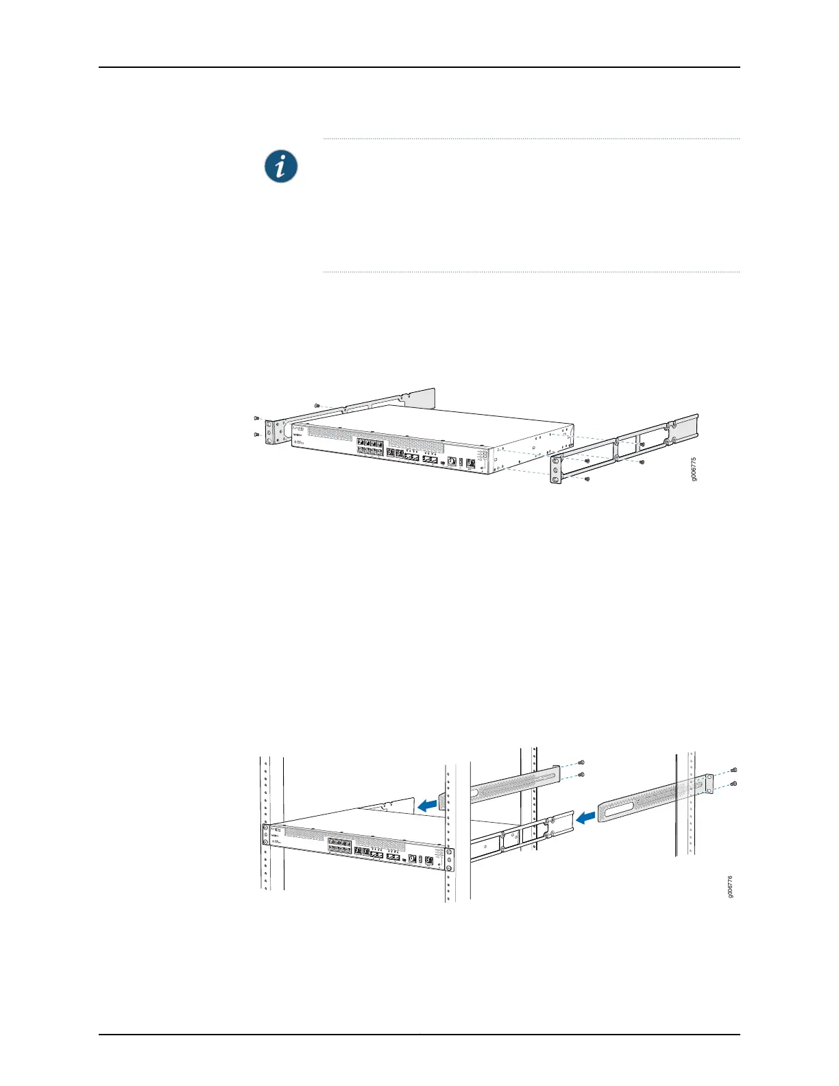
Figure 14: Attaching the Front-Mounting Bracket to the Chassis
4. Insert M4x6-mm Phillips flat-head mounting screws into the remaining two holes in
the front bracket and tighten the screws.
5. Repeat Step 2 through Step 4 for attaching the front-mounting bracket to the other
side of the chassis.
6. Have one person grasp both sides of the device, lift the device, and position it in the
rack, aligning the front bracket holes with the threaded holes in the front post of the
rack. Align the bottom hole in both the front-mounting brackets with a hole in each
rack rail, making sure the chassis is level. See Figure 15 on page 83.
Figure 15: Mounting the MX150 on the Front Posts in a Rack
7. Have a second person secure the front of the device to the rack by using the appropriate
screws for your rack.
83Copyright © 2017, Juniper Networks, Inc.
Chapter 10: Installing the MX150