Table 3: SRX4100 Services Gateway Components on the Front
Panel (continued)
DescriptionComponentNumber
Connects a laptop to the services gateway for CLI
management. The port uses an RJ-45 serial connection, is
configured as DTE, and supports the RS-232 (EIA-232)
standard.
Console port6
Returns the services gateway to the factory-default
configuration.
Reset button7
Chassis Status LEDs
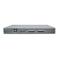
Figure 2 on page 6 shows the LEDs on the front panel, and Table 4 on page 6 describes
the LEDs.
Figure 2: SRX4100 Services Gateway Front Panel LEDs
Table 4: SRX4100 Services Gateway Front Panel LEDs
DescriptionLED
•
Solid green—receiving powerPower
•
Solid green—operating normally
•
Solid red—critical alarm
•
Hardware component failure
•
Software module failure
•
Fan failure (atleast one)
•
Blinking red—noncritical alarm
•
The other HA node is in the lost, disabled, or ineligible state.
•
Off—the system is not receiving power
Status
•
Blinking green—indicates hard disk drive (SSD) activitySSD
Management Port LEDs
The management port has two LEDs that indicate link activity and status of the
management port.
Table 5 on page 7 describes the LEDs.
Copyright © 2017, Juniper Networks, Inc.6
SRX4100 Services Gateway Hardware Guide