Figure 4: Network Port LEDs
Table 7: Network Port LEDs
DescriptionLEDCallout
•
Solid green—There is link activity.
•
Off—There is no link established.
Link (LED on the
left)
1
•
Solid amber—10 G/1 G link is established.
•
Blinking amber—There is activity on the 10 G/1 G link.
•
Off—There is no link established.
Speed/Activity
(LED on the
right)
2
Related
Documentation
Understanding the SRX4100 Services Gateway Back Panel on page 8•
• SRX4100 Services Gateway Physical Specifications on page 19
• SRX4100 Services Gateway Environmental Specifications on page 20
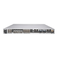
Understanding the SRX4100 Services Gateway Back Panel
Figure 5 on page 8 shows the back panel of the SRX4100 Services Gateway, and
Table 8 on page 8 lists and describes the back panel components.
Figure 5: SRX4100 Services Gateway Back Panel
Table 8: SRX4100 Services Gateway Back Panel Components
DescriptionComponentNumber
Connects the services gateway chassis to earth ground.Grounding point1
Use the Power switch to power on or power off the services
gateway.
Power switch2
Copyright © 2017, Juniper Networks, Inc.8
SRX4100 Services Gateway Hardware Guide