List of Figures
Part 1 Overview
Chapter 2 Chassis Components and Descriptions . . . . . . . . . . . . . . . . . . . . . . . . . . . . . . . 5
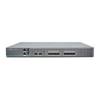
Figure 1: SRX4100 Services Gateway Front Panel . . . . . . . . . . . . . . . . . . . . . . . . . . . 5
Figure 2: SRX4100 Services Gateway Front Panel LEDs . . . . . . . . . . . . . . . . . . . . . 6
Figure 3: HA Port LEDs . . . . . . . . . . . . . . . . . . . . . . . . . . . . . . . . . . . . . . . . . . . . . . . . 7
Figure 4: Network Port LEDs . . . . . . . . . . . . . . . . . . . . . . . . . . . . . . . . . . . . . . . . . . . 8
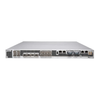
Figure 5: SRX4100 Services Gateway Back Panel . . . . . . . . . . . . . . . . . . . . . . . . . . 8
Chapter 3 Cooling System Description . . . . . . . . . . . . . . . . . . . . . . . . . . . . . . . . . . . . . . . . . 11
Figure 6: Airflow Through the Chassis . . . . . . . . . . . . . . . . . . . . . . . . . . . . . . . . . . . . 11
Chapter 4 Power Supply Description . . . . . . . . . . . . . . . . . . . . . . . . . . . . . . . . . . . . . . . . . . 13
Figure 7: AC Power Supply . . . . . . . . . . . . . . . . . . . . . . . . . . . . . . . . . . . . . . . . . . . . 13
Figure 8: AC Power Supply LEDs . . . . . . . . . . . . . . . . . . . . . . . . . . . . . . . . . . . . . . . 14
Figure 9: DC Power Supply . . . . . . . . . . . . . . . . . . . . . . . . . . . . . . . . . . . . . . . . . . . . 15
Figure 10: DC Power Supply LEDs . . . . . . . . . . . . . . . . . . . . . . . . . . . . . . . . . . . . . . . 15
Part 2 Site Planning and Specifications
Chapter 5 Planning and Preparing the Site . . . . . . . . . . . . . . . . . . . . . . . . . . . . . . . . . . . . . 19
Figure 11: Airflow Through the Chassis . . . . . . . . . . . . . . . . . . . . . . . . . . . . . . . . . . . 26
Chapter 6 Power Specifications and Requirements . . . . . . . . . . . . . . . . . . . . . . . . . . . . . 29
Figure 12: AC Plug Types . . . . . . . . . . . . . . . . . . . . . . . . . . . . . . . . . . . . . . . . . . . . . 30
Part 3 Initial Installation and Configuration
Chapter 10 Installing the Services Gateway . . . . . . . . . . . . . . . . . . . . . . . . . . . . . . . . . . . . . 41
Figure 13: Attaching the Mounting Ears and Fixed Brackets . . . . . . . . . . . . . . . . . . 43
Figure 14: Securing the Mounting Ears to the Rack . . . . . . . . . . . . . . . . . . . . . . . . . 43
Figure 15: Attaching the Adjustable Brackets . . . . . . . . . . . . . . . . . . . . . . . . . . . . . 44
Figure 16: Securing the Adjustable Brackets to the Rack . . . . . . . . . . . . . . . . . . . . 44
Chapter 11 Connecting the SRX4100 Services Gateway to Ground . . . . . . . . . . . . . . . . 45
Figure 17: Connecting the Grounding Cable . . . . . . . . . . . . . . . . . . . . . . . . . . . . . . 46
Chapter 12 Connecting the SRX4100 Services Gateway to Power . . . . . . . . . . . . . . . . . 47
Figure 18: Connecting AC Power . . . . . . . . . . . . . . . . . . . . . . . . . . . . . . . . . . . . . . . 48
Figure 19: Connecting DC Power . . . . . . . . . . . . . . . . . . . . . . . . . . . . . . . . . . . . . . . 50
Part 5 Replacing Components
Chapter 17 Replacing AC Power Supplies . . . . . . . . . . . . . . . . . . . . . . . . . . . . . . . . . . . . . . . 67
viiCopyright © 2017, Juniper Networks, Inc.