Table 6
The purpose of recommended back pressure is to avoid measuring errors as a result of cavitation or air in the
water.
It is not necessarily cavitation in the sensor itself, but also bubbles from cavitating pumps and regulating valves
mounted before the sensor. It can take some time before such bubbles have been absorbed by the water.
Furthermore, water can include dissolved air. The amount of air which can be dissolved in water depends on
pressure and temperature. This means that air bubbles can be formed due to pressure drop, e.g. caused by a
velocity rise in a contraction or above the meter.
The risk of these factors affecting accuracy is reduced by maintaining a fair pressure in the installation.
In relation to above table, the steam pressure at current temperature must also be considered. Table 6 applies to
temperatures up to approx. 80°C. Furthermore, it must be considered that the above-mentioned pressure is the
back pressure at the sensor and that the pressure is lower
under
a contraction than before
This can be explained by combining the continuity equation and Bernoulli’s equation. The total energy from the
flow will be the same at any cross section. It can be reduced to: P + ½ρv
one (e.g. cones). This
means that the pressure – when measured elsewhere - might be different from the pressure at the sensor.
2
When dimensioning the flow sensor you must take this into consideration, especially if the sensor is used within
the scope of EN 1434 between q
= constant.
p
and q
s
, and in case of heavy contractions of the pipe.
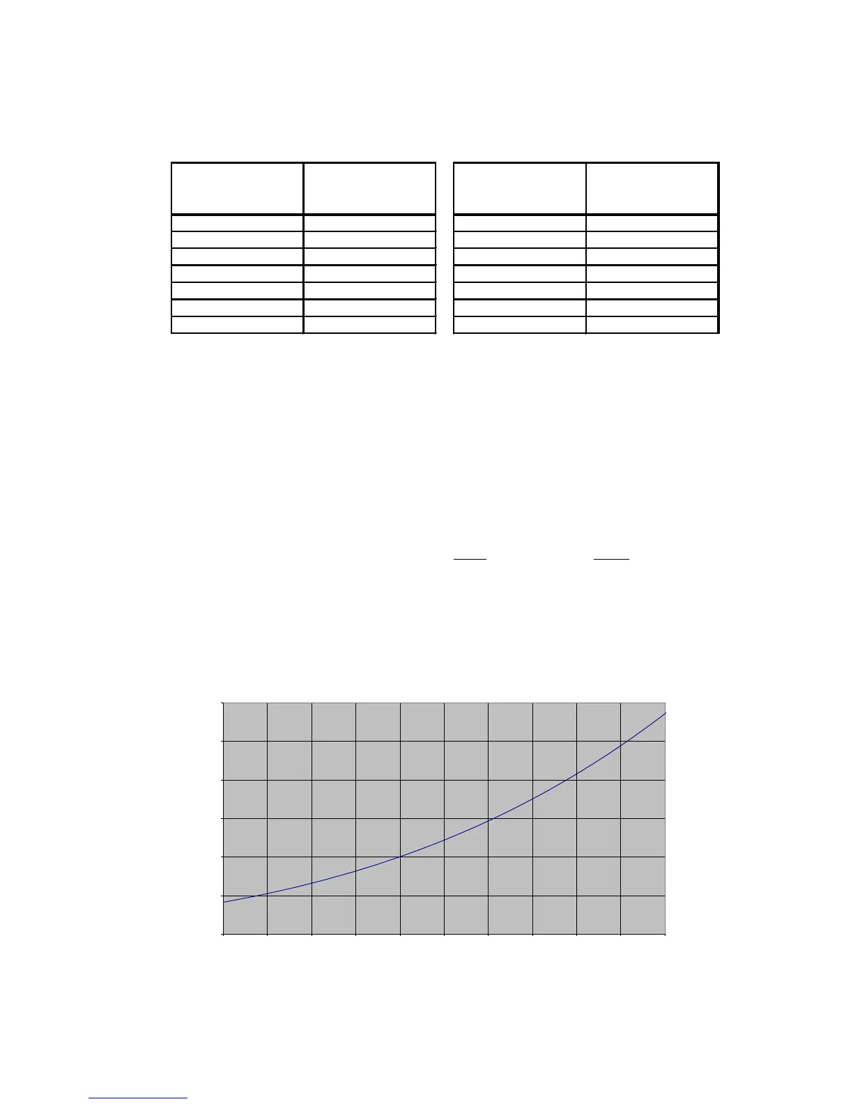
Diagram 3
0
0,5
1
1,5
2
2,5
3
80 85 90 95 100 105 110 115 120 125 130
[bar]
[°C]
Steam pressure