MULTICAL® 402
Kamstrup A/S · Technical Description · 5512-742_M1_GB_01.2016
85
13 Calibration and verification
To be able to carry out test/verification of MULTICAL
®
Note: MULTICAL
402 with minimum time consumption the meter has a
verification mode. When the meter is in verification mode, the program procedure is approx. four times faster than
in normal mode (like in fast mode). Furthermore, test mode includes some extra functions which are described
below.
®
The calculator can be calibrated either by means of ”Autointegration, as described in paragraph 13.2.5, or using
verification equipment type 66-99-372 /-373 together with the PC-program METERTOOL (see paragraph 14).
402 uses approx. twice as much current in verification mode. Under normal circumstances,
however, the meter will only be in verification mode e.g. 9 hours per five years, and this is without importance for
the meter’s total battery lifetime.
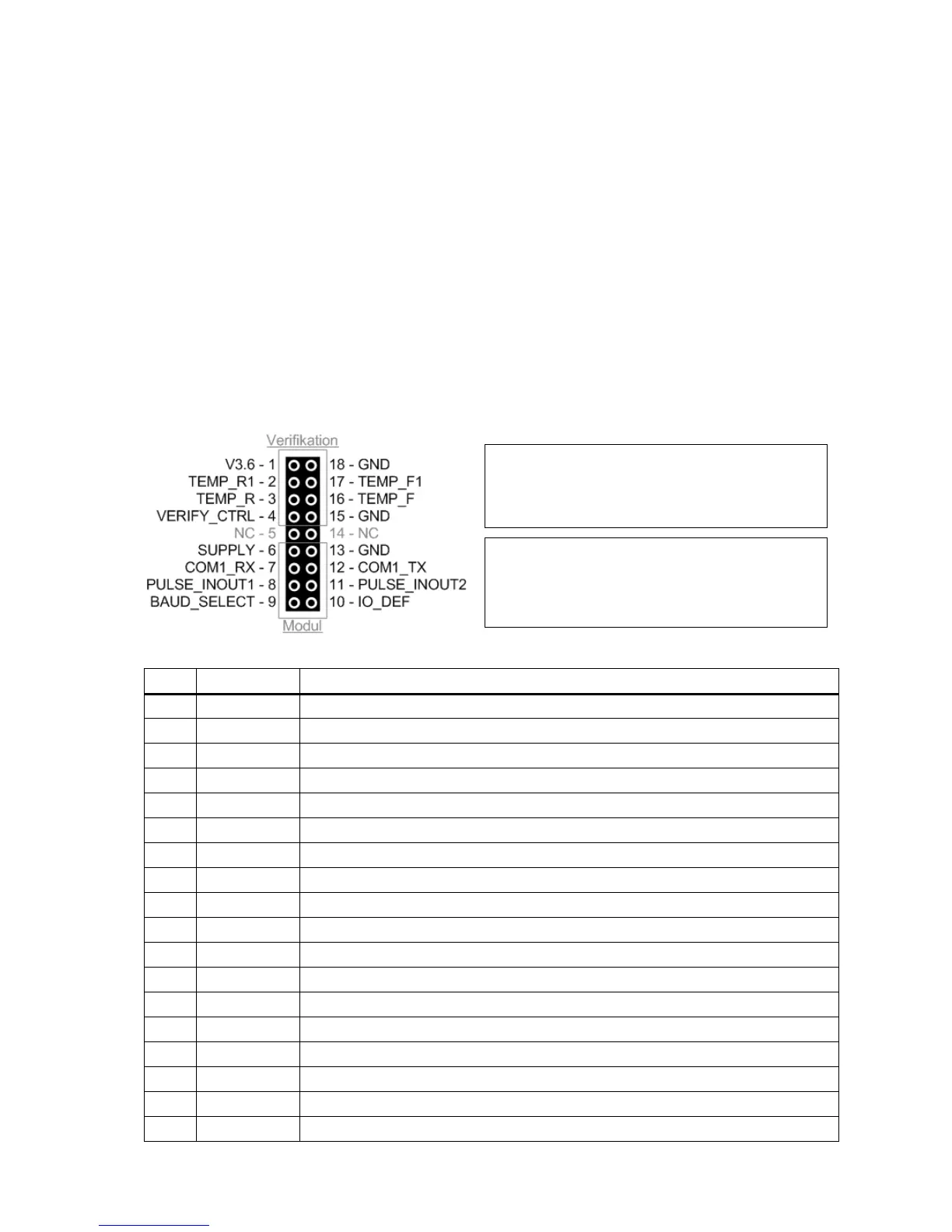
13.1 Connector
The verification and module connector is placed under the front cover and thereby sealed by the installation seal.
3.6 V internal supply on PCB. Connected to supply plug + pole via diode.
Return temperature, voltage input
Return temperature, current output
Verification control (legal lock). NC/V3.6 = locked; GND = open
Power supply direct connected to supply plug + pole.
Serial communication – meter’s RX
Pulse input A/output CE, depending on IO_DEF
Baud rate selector. NC/V3.6 = 1200; GND = 4800
Input/output definition. NC/V3.6 = inputs; GND =outputs
Pulse input B/output CV, depending on IO_DEF
Serial communication – meter’s TX
Forward temperature, current output
Forward temperature, power input
The upper part of the connector is used for
”verification”. This part is normally sealed to
prevent inadvertent access.
The bottom part of the connector is used for one of
the available plug-in modules for MULTICAL
®
402
(see paragraph 11). The module connector is
usually not sealed.