ACD320 user manual Appendix
- 131-
Odd parity
check bit
10 bit byte frame:
START Bit1 Bit2 Bit3 Bit4 Bit5 Bit6 Bit7
No paritycheck bit
Sto
p
bit
Even parity check bit
Odd parity check bit
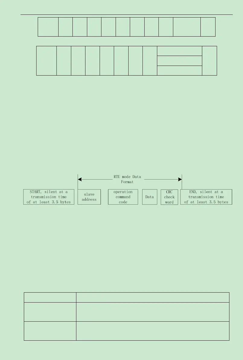
In RTU mode, new frames always become silent at a transmission time of at least 3.5 bytes,
as the start. Over a network using baud rate to calculate the transmission rate, the transmission
time of 3.5 bytes can be controlled easily. The subsequently transmitted data fields are in turn:
slave address, operation command code, data, CRC check word, the transmission bytes of each
field are 0 through 9 andA through F in hexadecimal notation.The network device monitors the
activities of the communication bus all the time, even during the silent interval. Once receiving
the first field (address message), each network device will confirm the byte.After the completion
of the transmission of the last byte, another transmission time interval similar to that of 3.5 bytes
is used to indicate the end of the frame.After that, the transmission a new frame starts.
The information of a frame should be transmitted in consecutive data streams. If there is an
interval over 1.5 bytes before the completion of the transmission of the entire frame, the
receiving device will clear the incomplete information, and mistake that the last byte is the
addressfield part of the new frame. Likewise, if the interval between the start of a new frame and
the previous frame is less than 3.5 bytes, the receiving device will regard it as the subsequent part
of the previous frame. Due to frame disorder, the final CRC value is incorrect, which will lead to
communication failure.
Standard Structure of RTU Frame:
Frame header (START) T1-T2-T3-T4 (transmission time of 3.5 bytes)
Slave address field
(ADDR)
Communication address:
0~247 (decimal) ("0" standsfor the broadcast address)
Function field
(CMD)
03H: Read slave parameters;
06H: Write slave parameters

 Loading...