ACD320user manual Installation and wiring
- 23-
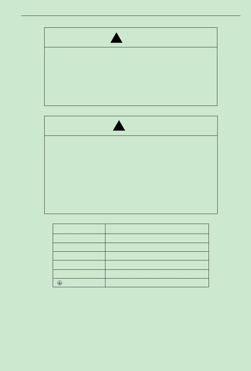
3. 4 Main Circuit Terminals andWiring
★Wiring can only be done after the mains input is cut off, otherwise therewill be
danger of electric shock!
★Only qualified and trained engineer can perform thewiring, otherwise there will be
danger of electric shock!
★Grounding cable must be grounded, otherwise there will be danger of electric shock
or fire!
★Please confirmthe mains voltage level is same with that of the inverter, otherwise the
inverter may be damaged!
★Make sure the ratings of the drivenmotor are in compliance with the inverter,
otherwise the motor may be damaged or the inverter may be in protection status!
★Do not confuse the input terminals with the output terminals (U, V,W), otherwise
there will be danger of damaging the inverter!
★Brake resistor cannot be connected between the DC bus terminals (+) and (-),
otherwise fire may occur!
(
1
)
Main Circuit Terminals of Inverter
Terminals Description
R/L1、S/L2、T/L3 AC input line terminals
B1、B2(DC+) Connection for the braking resistor (option)
P1/B2(DC+)、DC- Connection for the braking unit (option)
P1/B2(DC+)、P2 Connection for the DC Link Reactor (option)
(2)Notes on Wiring
A. Input power supply R/L1,S/L2 and T/L3:
There is no phase-ration requirement for the input of inverter.
B.DC bus P1/B2(DC+) and (DC-) terminals:
Pay attention that the DC bus terminals(P1/B2(DC+) and (DC-) still have voltage after power off,
and the user can only touch the terminals after the CHARGE LED turns off and the voltage is
below 36V, otherwise there is a danger of electric shock.