ACD320 user manual Parameter Description
- 84-
F4.08 Kick frequency range
0.0~50.0%(relative to
traverse frequency range)
0.0%
F4.09 Traverse frequency rising
time
0.1~3600.0s
5.0s
F4.10 Traverse frequency
descending time
0.1~3600.0s
5.0s
Traverse frequency function is suitable to industries such as textile, fiber and so on, and to
applications which require traversing andwinding functions.
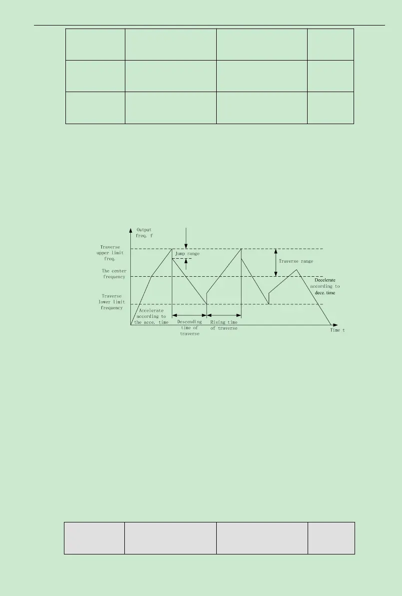
Traverse frequency function means that the inverter output frequency is traversing up and
down around the set frequency. The operating frequency locuswith time axis is shown as
following diagram, in which the amplitude of traverse is set by F4.07.When F4.07 is set to be 0,
i.e. traverse range is 0, the traverse frequency function will be inactive.
Fig. 6-15 Traverse Frequency Operation Diagram
Traverse frequency range: traverse operation frequency limits by upper and lower limit
frequency.
Traverse range relative to the center frequency: amplitude of traverseAW= CF
×
AWrange
F4.07
Kick frequency = amplitude of traverseAW
×
Kick Frequency Range F4.08. I.e. the kick
frequency is the value relative to amplitude of traverse at traverse-frequency operation.
Traverse frequency rising time: the time required to rise from the lowest traverse frequency
to the highest traverse frequency.
Traverse frequency fall time: the time required to fall from the highest traverse frequency to
the lowest traverse frequency.
Function Code Name Setting Range
Default
Value