ACD320user manual Digital Keypad Operation
- 33-
Chapter 4 Digital Keypad Operation
4.1 Description of the DigitalKeypad
DigitalKeypad Parts and Functions
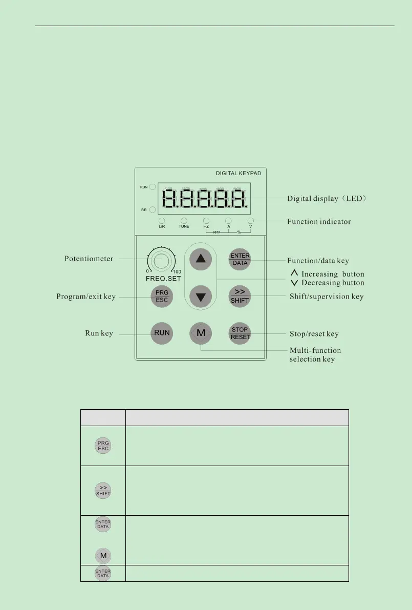
This digital keypad module includes two parts: display panel and a keypad.The display
panel allows the user to program the AC drive, aswell as view the different operating parameters.
The keypad is the user interface to the AC motor drive. Refer to the following figure for a
description of the different parts.
Fig. 4-1 Operation Panel Schematic Diagram
Table 4-1 keypad function table
Key Description
First-stage menu entry or exit
Under stop and run display interface, the display parameter can be
chosen by moving to the right circularly; when the parameter is
modified, its modified bit can be chosen, please refer to F3.05 ,
+
Under stop and run display interface, the display parameter can be
chosen by moving to the left circularly; when the parameter is
modified, its modified bit can be chosen, please refer to F3.05 ,
Enter into the next menu or setting parameter confirmation