ACD320 user manual Appendix
- 148-
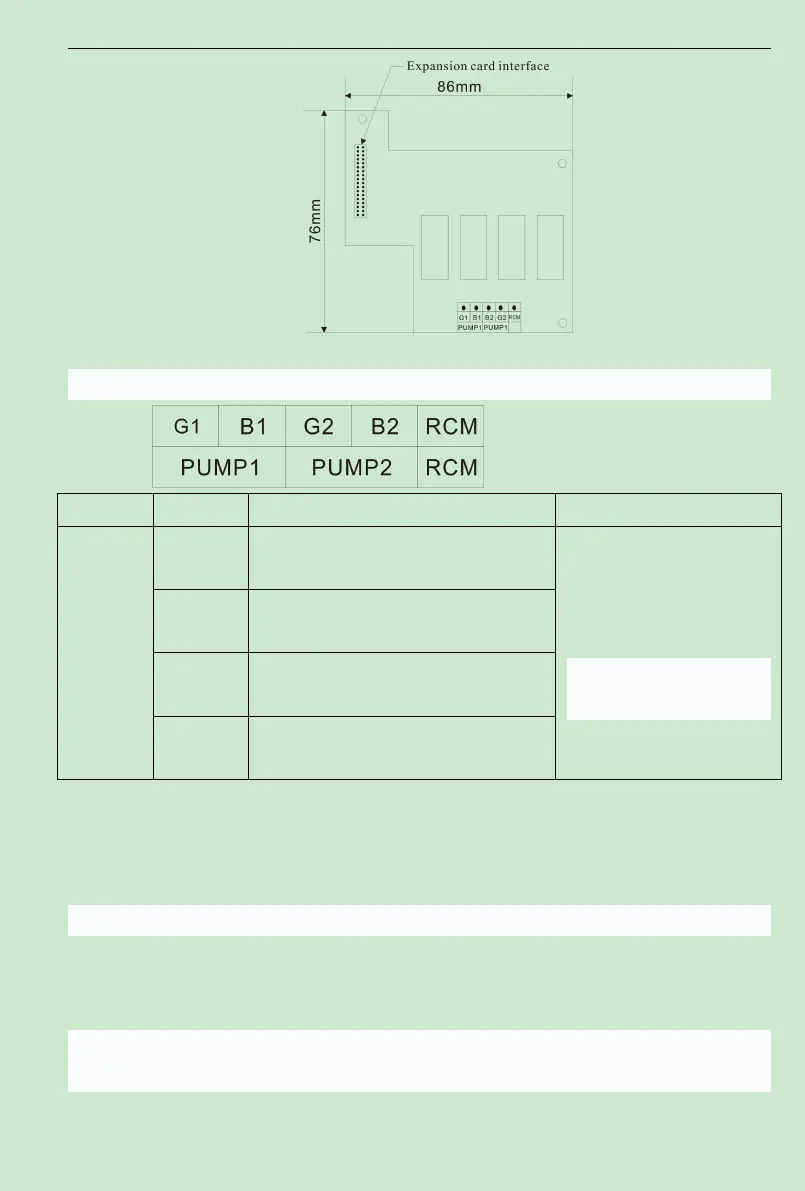
Fig. 9-2 Diagram for the size of one driving two constant pressure water supply card
3
.
Control terminals and wiring
Item Symbol Name Function description
Relay
output
terminal
B1-RCM
Relay output always-open terminal, the 1st
pump of variable frequency
conductor control the output
Contact capacity:
AC 3 8 0V/ 3 A , DC3 0 V / 1A 、
G1-RCM
Relay output always-open terminal, the 1st
pump of AC power
B2-RCM
Relay output always-open terminal, the 2nd
pump of variable frequency
G2-RCM
Relay output always-open terminal, the 2nd
pump of AC power
4
.
Function parameters
Please refer to appendix 3, and details is referred in F4 and F7.
5
.
Example for water supply mode that one for use and one for supplement
(
one driving two
circularly running
)
5.1 Process requirements
(
1
)
Water supply mode that one for use and one for supplement
(
one driving two
circularly running
)
(
2
)
Sleep and revival function to save energy
。
(
3
)
Timing switch of two pumps to prevent rust.
5.2 Equipment of the pump
Equipment of twice water supply system of the structure is as follows: