ACD320 user manual Parameter Description
- 72-
clear, and the given frequency will return to that the frequency
command channel has given, while it will to the frequency value
after the increasing/decreasing set.
Function Code Name Setting Range
Default
Value
F2.07
Terminal cont rol
mode
0: two-wirecontrol 1
1: two-wirecontrol2
2: three-wire control 1
3: three-wire control 2
0
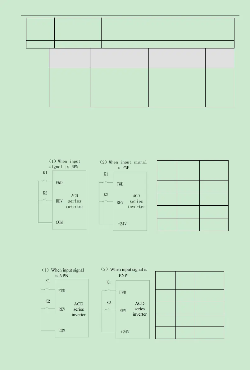
This parameter defines four different control modes which controls the inverter operation
through external terminals.
0: Two-wire type control, integrate Enable with direction. This mode is the most often used
two-wire controlmode. The motor forward and reverse operations are determined by the defined
FWD and REV terminal command.
Fig. 6-8 Two-wire operation mode 1
1: Two-wire control, separateEnable fromdirection.When thismode is used, the defined
FWDis enable terminal. The direction is determined by the defined REVstate.
Fig. 6-9 Two-wire operation mode 2
OFF OFF STOP
ON OFF FWD
OFF ON REV
ON ON STOP