ACD320 user manual Parameter Description
- 63-
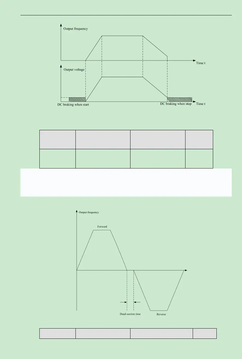
Fig. 6-3 DC Brake Diagram
Function Code Name Setting Range
Default
Value
F0.24
Dead time between
forward and reverse
0.0~3600.0s 0.0s
In the transition process when the inverter runs transforming between forward and reverse,
the transition time that the output frequency is 0 is as follows:
Fig. 6-4 FWD/REV Dead Time Diagram
Function Code Name Setting Range Default