ACD320 user manual Parameter Description
- 91-
the detecting time exceeds the feedback disconnected detecting time, the system will send an
alert of feedback disconnecting failure . (U-25)
Function Code Name Setting Range
Default
Value
F4.29 Multi-Speed 0 -100.0~100.0% 0.0%
F4.30 Multi-Speed 1 -100.0~100.0% 0.0%
F4.31 Multi-Speed 2 -100.0~100.0% 0.0%
F4.32 Multi-Speed 3 -100.0~100.0% 0.0%
F4.33 Multi-Speed 4 -100.0~100.0% 0.0%
F4.34 Multi-Speed 5 -100.0~100.0% 0.0%
F4.35 Multi-Speed 5 -100.0~100.0% 0.0%
F4.36 Multi-Speed 7 -100.0~100.0% 0.0%
Note: The multi-speed symbol defines the operation direction. If it is negative, the operation
direction is reverse. Frequency setting 100.0% is corresponding to maximum frequency(F0.04).
When MI1=MI2=MI3=OFF
,
the input mode is chosen by F0.03. When terminals MI1
、
MI2
、
MI3 are not all OFF and multi-step speed run, priority of multi-step speed is higher than the
input of keyboard,simulation and communication frequency, through the combined code, 8-step
speed can be chosen at most.
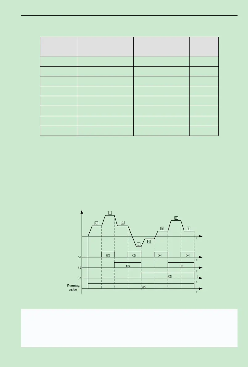
Fig.6-20multi-speed logic Diagram
The selection of stop channel starting is also determined by function code F0.01 when
inverter is running at multi- speed, and the multi- speed control process is shown in Fig.6-20.
The relation between MI1
、
MI2
、
MI3 terminal and multi-speed section is shown in the following
table.