ACD320 user manual Parameter Description
- 69-
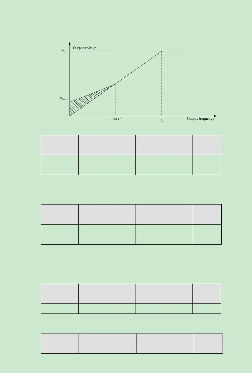
Torque boost cut-off frequency: below this frequency, torque boost is valid, and above this
frequency setting, torque boost is invalid.
Fig. 6-7Manual torque boost diagram
Function Code Name Setting Range
Default
Value
F1. 23
V/F slip
compensation limit
0.0~200.0% 0
Setting this parameter can compensate the motor speed change produced because of
undertaking loading while on V/F control, to increase the rigidity of motor mechanical
performance. This value should be set as the motor rated slip frequency.
Function Code Name Setting Range
Default
Value
F1. 24
Energy Conservation
Selection
0: No Operation
1: Energy Conservation
0
When the motor is running in no-load or lower-load during,the inverter can output voltage
by adjust automatically current kf the load。
Note:This function is especially valid for variable torque load (such as fan and pump).
6.3 F2 Input and Output Terminal Function Parameters
Function Code Name Setting Range
Default
Value
F2.00 On-off signal filter times 1~10 5
It sets up MI1~MI6,AVI and ACI terminals sample filtering time. In big interference
situation, this parameter should be increased in order to preventmal operation.
Function Code Name Setting Range
Default
Value