ACD320 user manual Parameter Description
- 73-
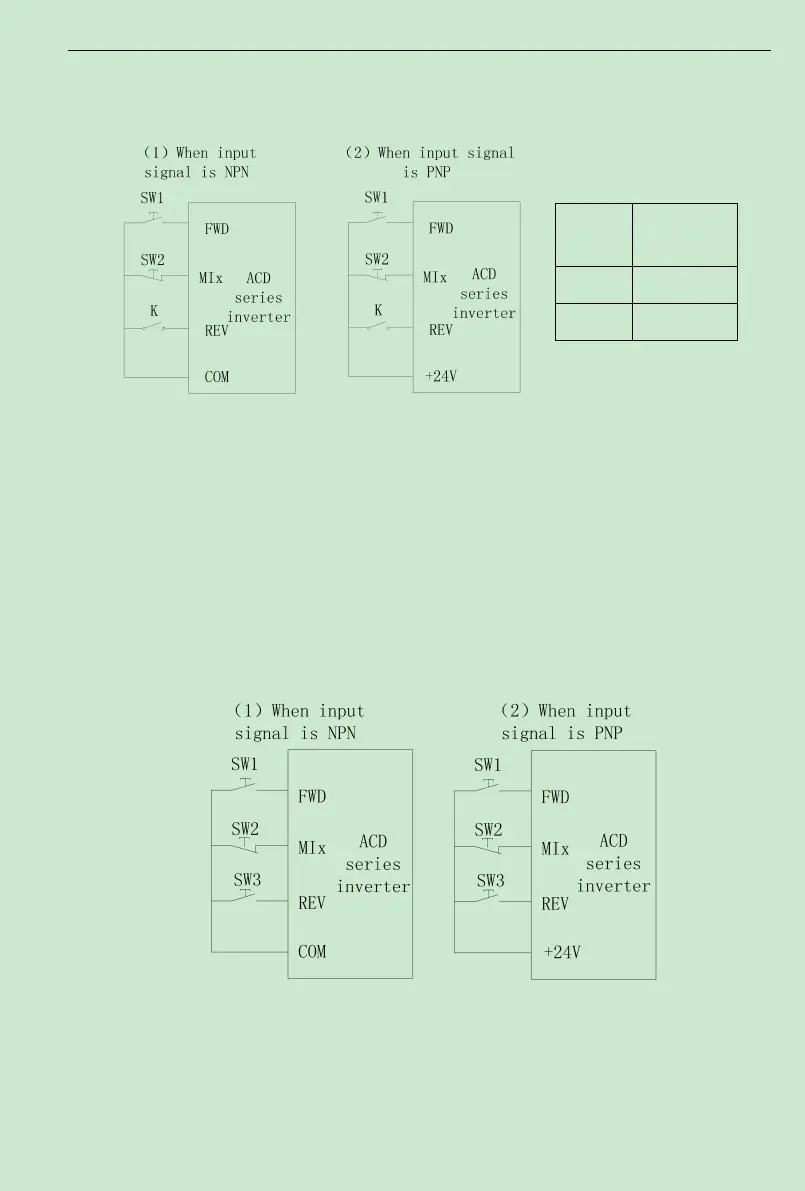
2: Three-wire control 1, integrate Enable with direction.At thismode, EN is the Enable
terminal with the direction controlled by the defined FWD. REV define the direction.
Fig. 6-10 Three-wire operation mode 1
K: FWD/REV switch SW1: RUN button SW2: STOP button
MIx is defining the corresponding terminal function as Function 3 “Three-wire operation
control ”.
3: Three-wire control, separate Enable from direction.At thismode EN is the Enable
terminal, SW1 or SW3 define operating command and control direction at the same time. Stop
command is defined by SW2.
Fig. 6-11 Three-wire operation mode 2
SW1: FWD operating button SW2: STOP button K: REVoperating button
MIx is defining the corresponding terminal function as Function 3 “Three-wire operation
control ”.
K
Operation
Command
OFF FWD
ON REV