ACD320user manual Installation and wiring
- 27-
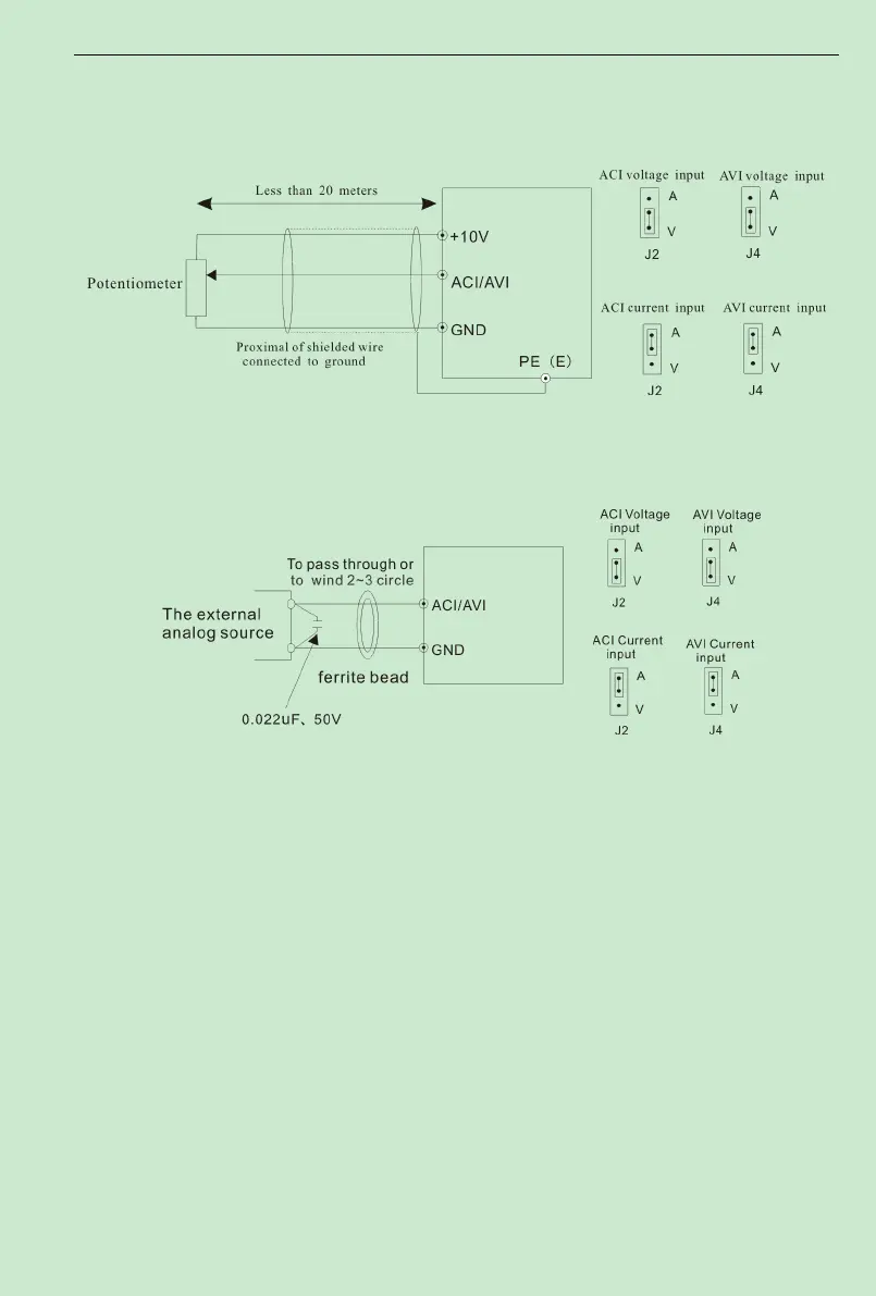
cable shall be used and the cable shall be as short as possible and the length shall not exceed 20m,
as shown in the figure 3-6:
Fig. 3 -6 Analog Input Terminal of ACD Series Inverter
If the analog signal is severely disturbed, filter capacitor or ferrite core shall be installed at the
analog signal source as shown in the Fig. 3-7
:
Fig. 3-7 Analog Input TerminalWith Filter devices
(2) Analog output terminal wiring
Analog output terminal AO1, AO2 connected to analog meter and kinds of physical
data can be indicated, thereinto AO1 can output current(0~20mA) or voltage(0~10V)
decided by jumping-wire J3, AO2 can output current(0~20mA) or voltage(0~10V) decided
by jumping-wire J5. Terminal wiring mode as Fig.3-8.