ACD320 user manual Parameter Description
- 68-
vector control.
Function Code Name Setting Range
Default
Value
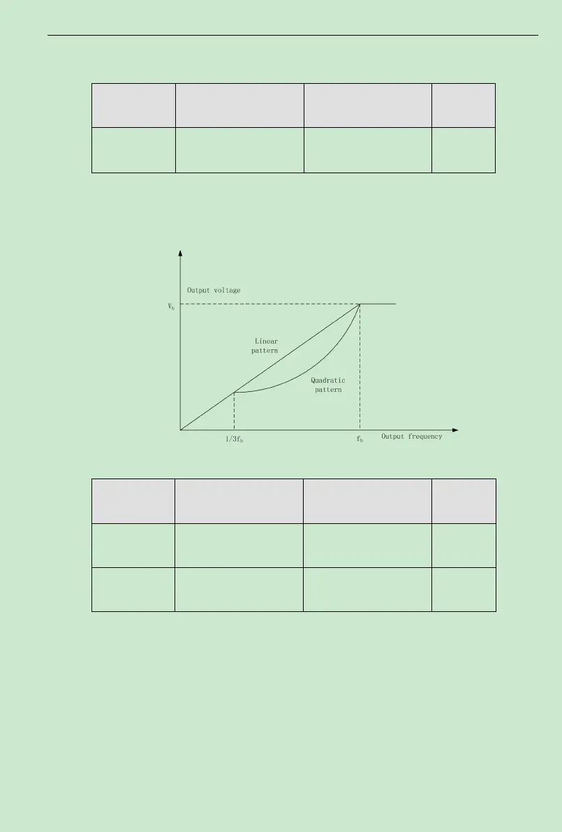
F1.20 V/F curve setting
0: LinearV/Fcurve
1: square torque V/F curve
0
0: LinearV/F curve. It is applicable to constant torque load.
1: 2.0 exponential V/F curve. It is applicable to variable torque load, such as blower,
pump etc.
Fig. 6-6 V/F curve
Function Code Name Setting Range
Default
Value
F1. 21 Torque boost
0.0%:(auto) 0.1 % ~ 30.0
%
0
F1. 22 Torque boost cut-off
0.0% ~ 50.0% (relative to
motor rated frequency)
20.0%
Torque Boost is mainly applied to less than cut-off frequency (F1.22). TheV/F curve after
boost is shown in following figure. Torque booth can improve the low frequency torque
performance ofV/F control.
Based on the load, a torque should be chosen properly. For heavy load, increase the torque
boost, but the torque boost should not be set too big, whichwill result in the motor operating at
overexcitation and that it could be overheated, and also the inverter output current is big,
reducing efficiency.
When the torque boost is set as 0.0%, the inverter is at automatic torque boost.