ACD320 user manual Appendix
- 132-
DATA(N-1)···DATA
(0)
Data of 2*N bytes: this part is the main content of
communications, and is also the data exchange core in
communications.
CRC CHK lower bit
Detection value: CRC value (16BIT).
CRC CHK higher bit
Frame tail END T1-T2-T3-T4 (transmission time of 3.5 bytes)
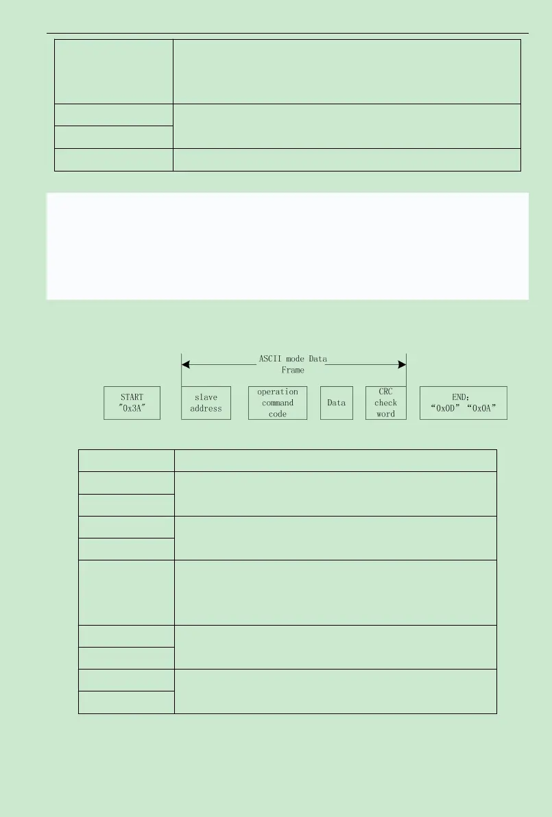
In ASCII mode, frame header is ":" "0x3A" ,frame tail is "CRLF" "0x0D""0x0A").Except frame
header and frame tail, all other bytes are transmitted by ASCII coding system. It will transmit
high4 bits first, then transmit low 4 bits. The data length is 7 or 8 bit in ASCII mode. Capital
ASCII is used to demonstrate 'A'~'F' and use LRC check, cover the information from slave
address to data. The checksum is equal to the radix complement of the sum of all characters
involved in checking the data.
ASCII frame standard structure
START ‘:’(0x3A)
Address Hi
Communication address: 2 ASCII combine 8-bit address
Address Lo
Function Hi
Function code:
2ASCII combine 8-bit address
Function Lo
Data content:
nx8-bit 2nASCII combine data content
n<=16,maximum 32ASCII
LRC CHK Hi
LRC check:
2 ASCII combine 8-bit check code
LRC CHK Lo
END Hi
End:END Hi=CR(0x0D),END Lo=LF(0x0A)
END Lo
6. Command Codes and Communication Data
6.1Command Code: 03H (0000 0011), read N words (can ready a maximum of consecutive five

 Loading...