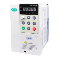
ACD320 user manual Parameter Description
- 92-
Relationship betweenmulti-speed and MI1
、
MI2
、
MI3 terminals:
MI1 MI2 MI3
Current segment of
multi-speed control
OFF OFF OFF Multi-Speed 0
ON OFF OFF Multi-Speed 1
OFF ON OFF Multi-Speed 2
ON ON OFF Multi-Speed 3
OFF OFF ON Multi-Speed 4
ON OFF ON Multi-Speed 5
OFF ON ON Multi-Speed 6
ON ON ON Multi-Speed 7
6.6 F5 Protection Parameters
Function Code Name Setting Range
Default
Value
F5.00
Motor Overload
Protection Option
0: Noprotection
1: normal motor
2: Variable
Frequencymotor
1
0: no protection. There is nomotor overloading protection characteristic (caution to use),and
thereby the inverter has no protection to the overloaded motor.
1: normalmotor (with low speed compensation).As generalmotor has a poor heat emission at
low speed, the relevant electronic thermal protection should be regulated properly.The low speed
compensation characteristic herementioned is to switch down the overloading protection
threshold for themotor with an operation frequency lower than 30 Hz.
2:Variable frequencymotor (without lowspeed compensation).As the heat emission of
special variable frequency motor is not affected by speed, it is not required to regulate the
protection value for lowspeed operation.
Function Code Name Setting Range
Default
Value
F5.01
Motor Overload
Protection Current
20.0% ~ 120.0%(motor
rated current)
100.0%

 Loading...