ACD320 user manual Parameter Description
- 75-
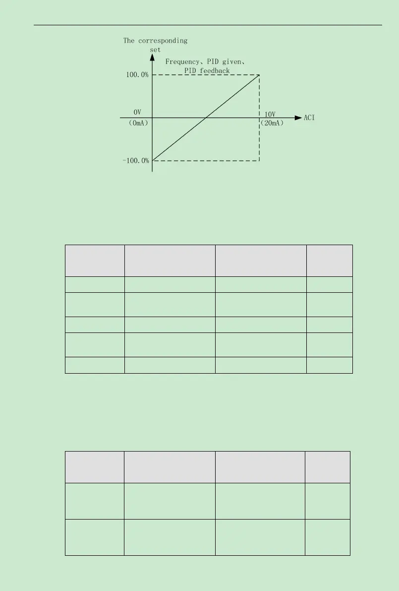
Fig. 6-12Relationship between analog input and setting value
AVI input filtering time determines analog input sensitiveness. Increasing this parameter, in
order to prevent malfunction caused by interference to the analog, can strengthen the
anti-interference ability, but reduce the analog input sensitiveness.
Function Code Name Setting Range
Default
Value
F2.14
0.00V~10.00V 0.30V
F2.15
-100.0%~100.0% 0.0%
F2.16
0.00V~10.00V 9.70V
F2.17
-100.0%~100.0% 100.0%
F2.18
0.00s~10.00s 0.10s
ACI function settings are similar toVI setting method.
ACD320 Series inverter provides 2 paths of analog input port.
ACD320 Series inverter standard unit has twomultifunction digital output terminal, one (or
two) multifunction relay output terminals and one analog output terminal.
Function Code Name Setting Range
Default
Value
F2.19
0~24 3
F2.20
0~24 3