ACD320user manual Installation and wiring
- 28-
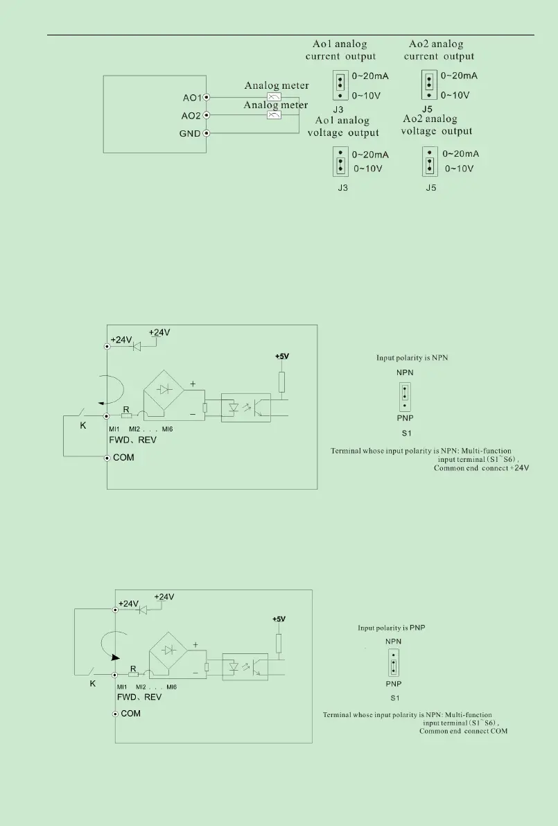
Fig.3-8 Analog output terminal wiring diagram
(
3
)
MI1
~
MI6
、
FWD
、
REV terminal wiring method
A. the mode of dry contact
①
Use interior 24V power supply, when input polarity is PNP
,
the wiring mode as
Fig.3-9.
Fig.3-9 Source Electrode Connection mode when using interior 24V power supply
②
Use interior 24V power supply, when input polarity is PNP
,
the wiring mode as
Fig.3-10.
Fig.3-10 Drain electrode connection mode when using interior 24V power supply
B. Source(Drain) Electrode Connection