ACD320user manual Installation and wiring
- 29-
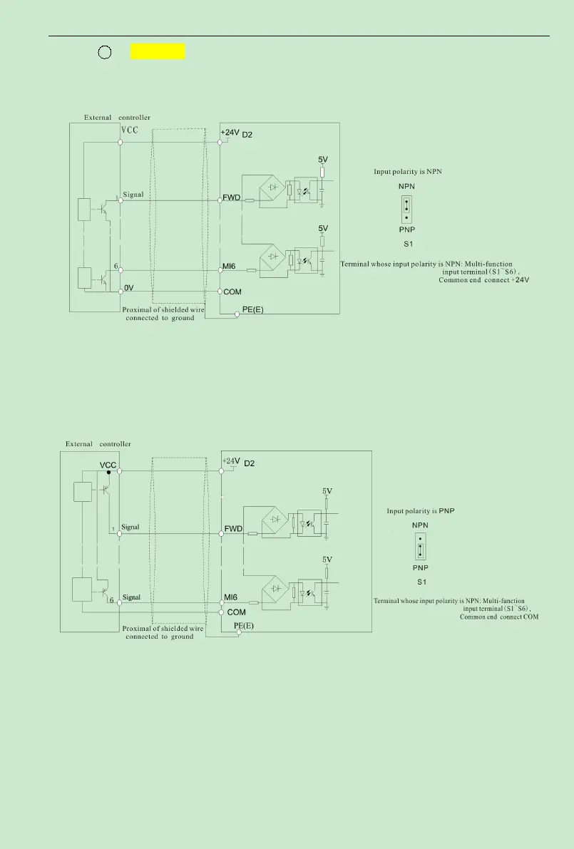
1 The use of inverter internal +24V power supply, external controller for
NPN typecommon emitter connection pole output
,
As shown in Figure 3-11
。
Fig.3-11 Source Electrode Connection mode when using interior 24V power supply
②
The use of inverter internal +24V power supply, external controller for
PNP typecommon emitter connection pole output
,
As shown in Figure 3-12
。
Fig.3-12 Drain electrode connection mode when using interior 24V power supply
(
4
)
Number output terminal DO
When number output terminal need to drive the delay, absorber diode should be added to the
two sides of delay coil, else DC 24V power supply may be damaged.
Note: The absorption diode shall be installed with correct polarity, as shown in Fig.3-13.
 Loading...