ACD320 user manual Parameter Description
- 77-
21
Simple PLC run for a
cycle
After simple PLC run for a cycle, output impulse signal of
500ms.
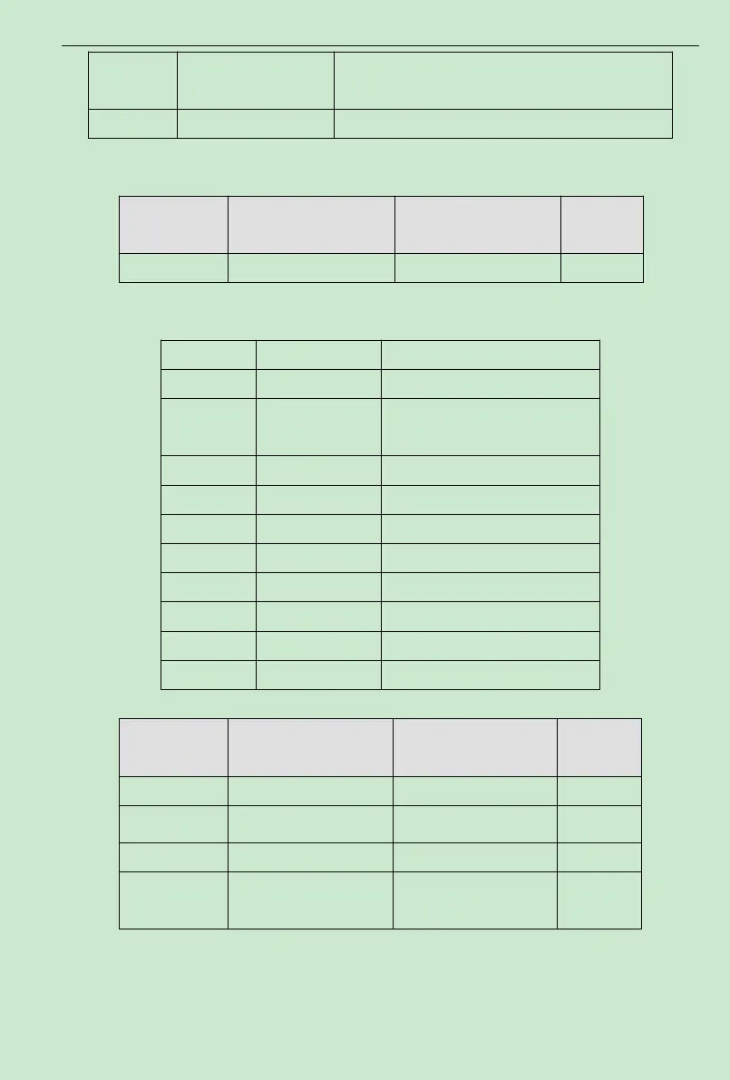
22~24 Reserved Reserved
Function Code Name Setting Range
Default
Value
F2.22 AO1 output selection 0~10 0
The standard analog output is 0-20mA(or 0-10V). Current or voltage output can be selected
by Jumper S2. Its corresponding value range is shown as following table:
Setting Value Function Range
0 Setting frequency 0-maximum output frequency
1
Operating
frequency
0-maximum output frequency
2 Output current 0-double rated inverter current
3 Output voltage 0-1.5 times rated inverter voltage
4 Motor speed 0-double rated motor speed
5 Output power 0-double rated power
6 Output torque 0-double rated motor current
7 Analog AVI input 0~ 10V/0~20mA
8 Analog ACI input 0~ 10V/0~20mA
9~10 Reserved Reserved
Function Code Name Setting Range
Default
Value
F2.23
0.0%~100.0% 0.0%
F2.24
Lower limit corresponding
0.00V~10.00V 0.00V
F2.25
0.0%~100.0% 100.0%
F2.26
Upper limit corresponding
AO1 output 0.00V~10.00V 10.00V
Above function codes define the relationship between output value and analog output
corresponding output value.When the output value exceeds the maximum output or the minimum
output range, the beyond portion should be calculated with maximum output or minimum output.
 Loading...