220
CH - Conguration Handling
CH10 - 15: LED Diagnostics
The LEDs on the serial operator are used to indicate operational status. In
addition they can be used for troubleshooting or diagnostics.
For each LED, a parameter will select whether the LED has its normal function
or is mapped to a special function. The tables below describe the function.
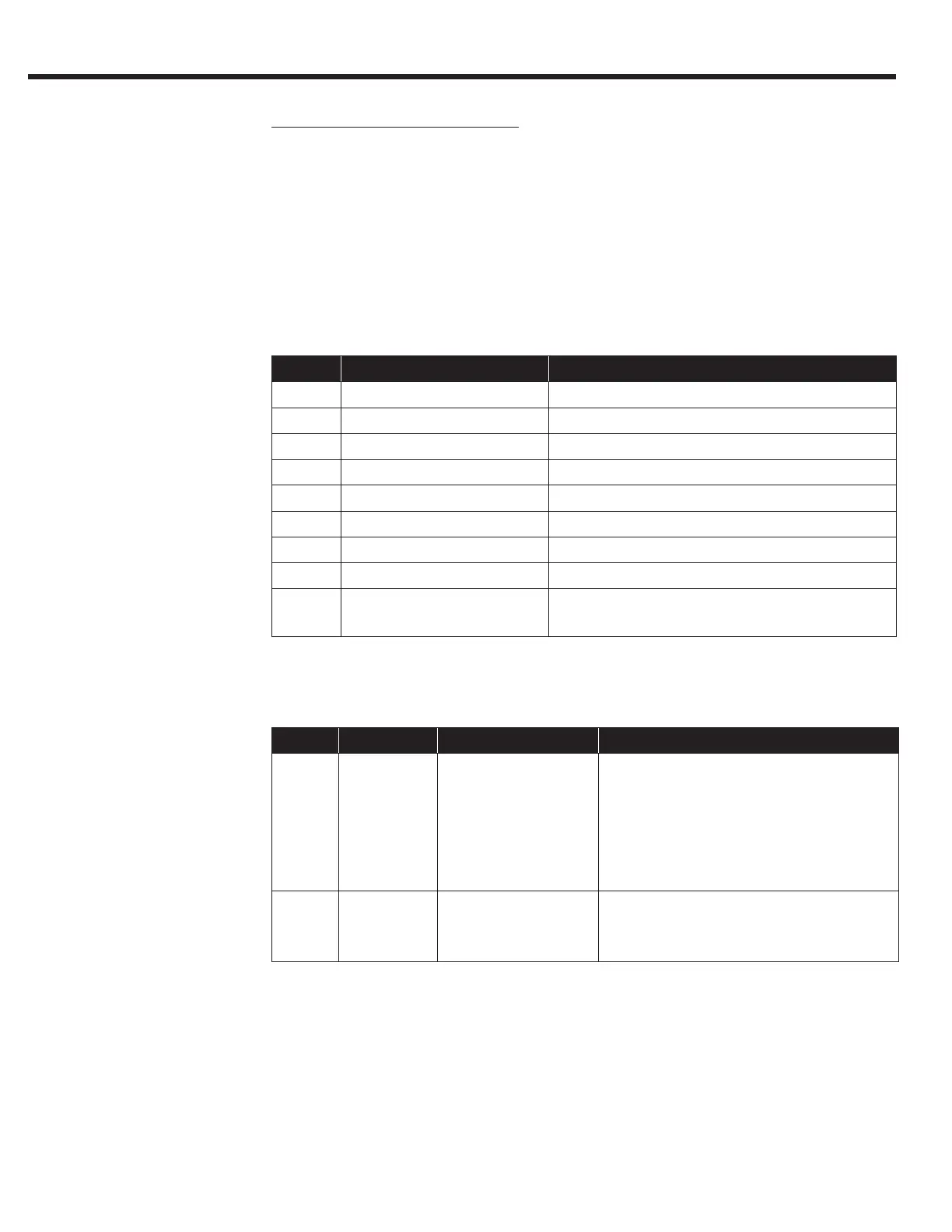
CH10 and CH13:
Value: Function: Description:
0 Default Normal Function The standard function
1 Input Status Bit 0-7 = I1 - I8 in Dg01
2 Output Status Bit 0-3 of Dg11
3 Output Condition Status Bit 0-7 of Dg16
4 Lift App Control Word Bit 0-31
5 Inverter Control Word Bit 0-15 of Sy50 (internal)
6 Field Bus Control Word Bit 0-15 of Fb01
7 CAN Bus Control Word Bit 0-15 of Fb43
8 Raw Memory Address Bit 0-31 of the address and bit in CH12
and CH13
CH11, 12 and CH14, 15:
Para: Value: Function: Description:
CH11
CH14
000000h -
FFFFFFh
Memory Address The memory address of the function
selected in CH.10 and CH.13.
This parameter auto populates
once CH.10 and CH.13 have been
dened and will not need further
adjustment.
CH12
CH15
0h -
7h
Data Size and Bit 00h-07h = bits 0-7 byte sized data
10h-1Fh = bits 0-15 word sized data
20h-3Fh = bits 0-31 long sized data
 Loading...


