40
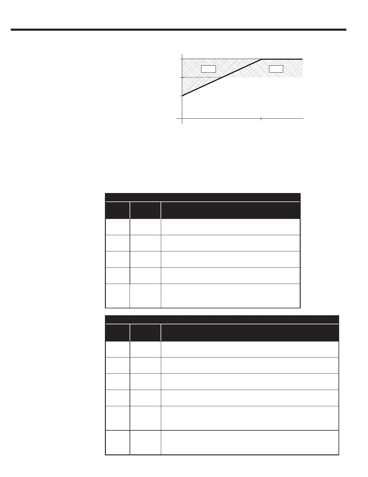
Overload Curves
Load [%]
Permanent
current
(0 Hz)
230V Maximum stall current (amps at 0Hz)
Inverter
Housing
Carrier
Frequency
Inverter Size
13 14 15 15+ 16 17 17+ 19 20 21 23
E 8 kHz 24 24
16 kHz 16.8 16.8
G 8 kHz 33 31 53
16 kHz 33 26 43
H 8 kHz 73 109 97
16 kHz 73 92 59
R 8 kHz 115 145 180
16 kHz 70 102 102
U 4 kHz 319
8 kHz 203
16 kHz -
480V Maximum stall current (amps at 0Hz)
Inverter
Housing
Carrier
Frequency
Inverter Size
13 14 15 16 17 18 19 20 22 22+ 24 26 26+ 28
E 8 kHz 12 16.5 16
16 kHz 12 10 10
G 8 kHz 19 22.0 21.5
16 kHz 8.4 9.5 -
H 8 kHz 42 50 54 83
16 kHz 25 30 36 45
R 8 kHz 115 150
16 kHz 63 98
U 4 kHz 198 330 330
8 kHz 180 180 225
16 kHz - - -
W 4 kHz 574
8 khz 407
16 kHz -
At low speeds (below 3 Hz G-W housings, below 6Hz D-E housings), the rms current owing
through the power transistors is higher, reaching 1.4 times the rated 60Hz rms value. This is
caused by the low-frequency sine wave created by the PWM. As a result, the continuous output
current must be limited at low speeds to prevent the power transistors from overheating. The
COMBIVERT F5 will drop the carrier frequency to 4kHz if necessary to be able to continue to
provide current to the motor. Once the output frequency rises above low frequency or the current
drops below the levels listed below, the carrier frequency will be returned to the higher value.
2.10 Error Overload Low Speed

 Loading...


