Connection of braking resistor
(Braking circuit installed as standard in
housing sizes E,G,H, R and U.)
External motor temperature sensor
(for all units)
Thermal switch
(NC-contact)
No jumper required,
when a sensor is not
connected
Temperature sensor (PTC )
1650Ω...4kΩ tripping resistance
750Ω...1650Ω reset resistance
Don't install sensor wires with control wires!
Must use a double shield when running these
wires with motor wires!
It is necessary to activate this function via
software parameter! See LX10
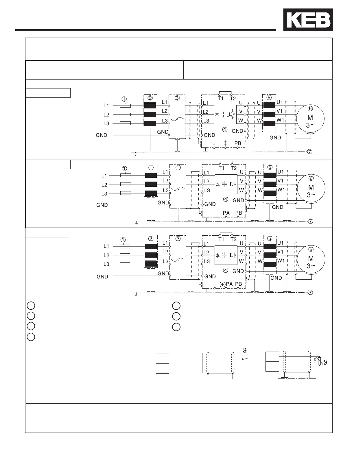
Wiring diagram 3
Supply fuse Motor Choke or Output Filter
Line Choke Motor
Interference Suppression Filter Sub-Panel in Control Cabinet
COMBIVERT F5
*Main disconnect /
feeder circuit not shown
If the supply voltage is connected to the motor
terminals, the unit will be destroyed!
Pay attention to the supply voltage 230/480V
and the correct polarity of the motor!
See technical data in Sections 2.4-2.5 to match the wiring diagram to inverter size and housing type.
Wiring diagram 1
Wiring diagram 2
2.8 Connection of the power circuit
2
3
*Main disconnect /
feeder circuit not shown
*Main disconnect /
feeder circuit not shown
IMPORTANT: See Section 2.2.4 for Fusing Specications
Refer to section 2.2.15 for wiring diagrams
Power Connections
35
1
2
3
4
5
6
7

 Loading...


