X6C X6D
X6C X6D
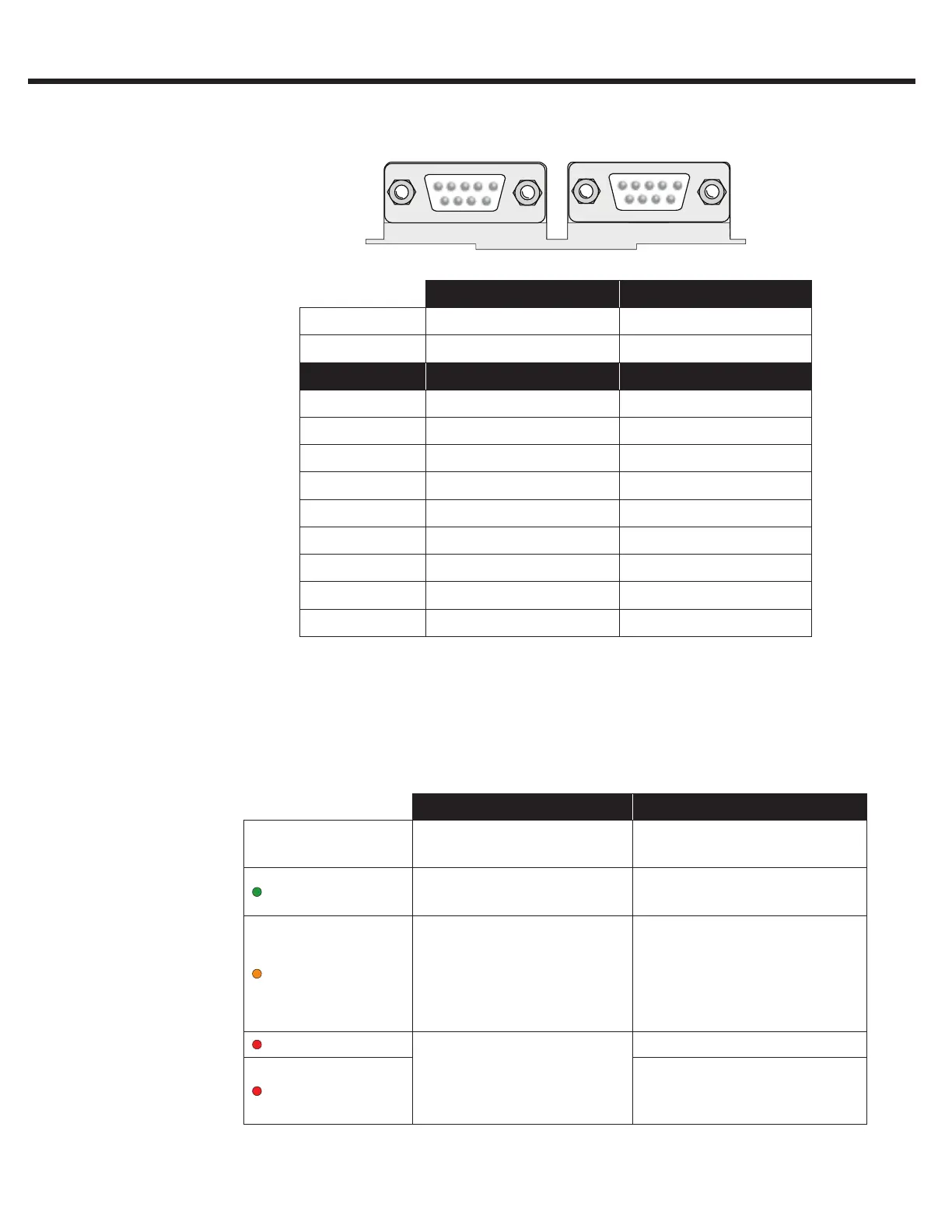
Hardware CAN | RS 485 RS 232/485
Use Bus Communications Diagnostics
Pin Signal Signal
1 CAN V+
2 CAN L TxD, RS232
3 CAN H RxD, RS232
4 RxD A -, RS485 RxD B +, RS485
5 RxD B +, RS485 RxD A -, RS485
6 CAN GND ) VP +5V (10mA)
7 Bus Ground Bus Ground
8 TxD A -, RS485 TxD B +, RS485
9 TxD B +, RS485 TxD A -, RS485
The LED indicators are available only on the Serial LCD Operator. The
LEDs are used to indicate operational status. They can be used for
troubleshooting and diagnostics. In addition, the function of the LED can
be changed with parameters CH10 - 15. Refer to Section 6.12 for additional
information on CH parameters.
LED 1 LED 2
Off
No operation (noP)
Drive not enabled
(Green)
Inverter running the
motor
Run mode
Drive is able to run
(Orange)
-
Stop mode:
Drive is being
programmed or making
calculations;
FTP le transfer mode.
(Red - Blinking)
A limit has been
reached: Torque,
Current, or Voltage (not
yet implemented)
-
(Red - Solid)
Drive is faulted
4.2 Serial/CAN
Hardware Version
4.2.1 LED Indicators
LCD Keypad
76

 Loading...


