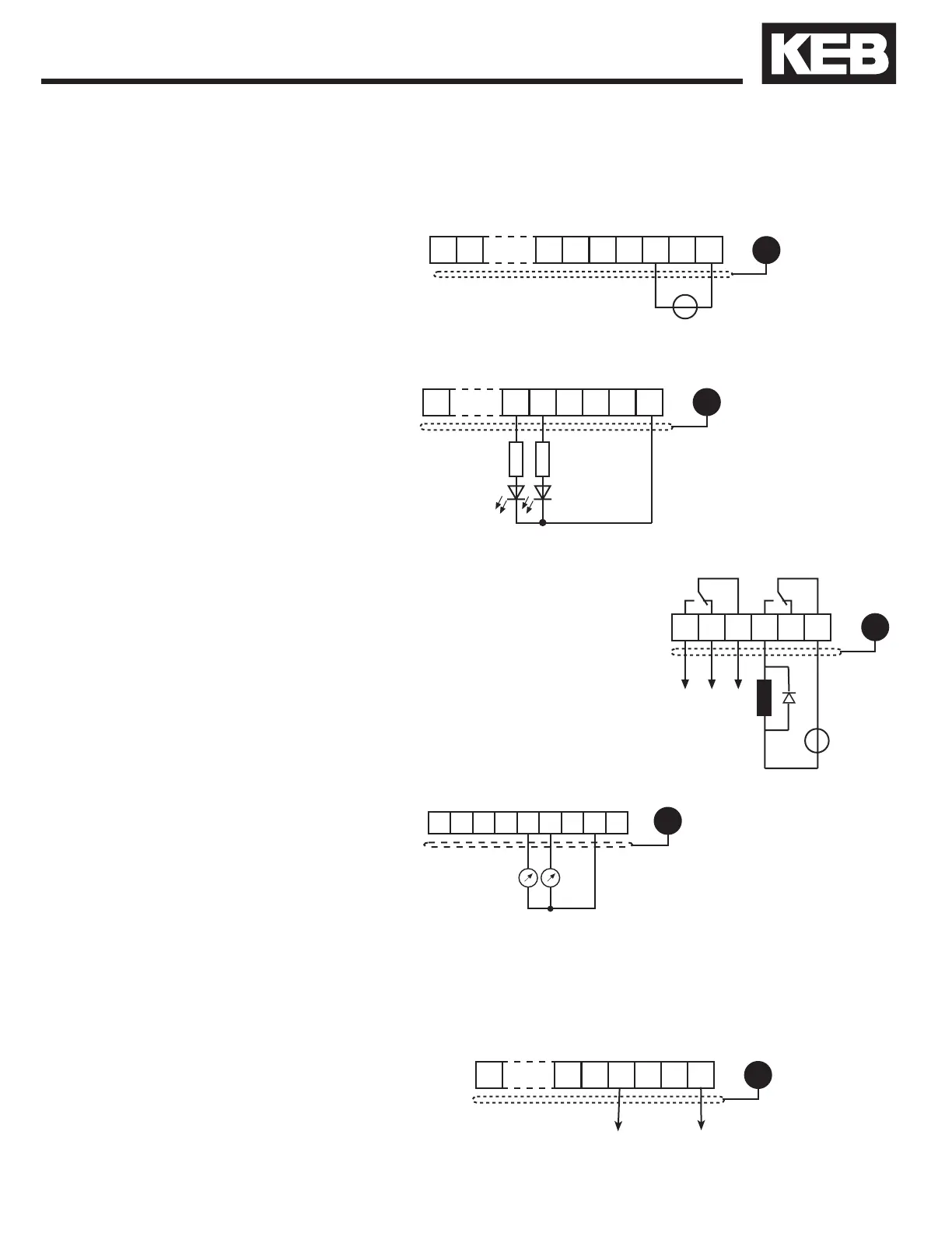
3.1.7 Relay Outputs
3.1.8 Analog Outputs
3.1.6 Digital Outputs
A total of max.
50 mA DC for
both outputs
3.1.9 Voltage Output
3.1.5 Voltage Input /
External Power Supply
The voltage output serves for triggering the digital inputs as well as for
supplying external control devices. Do not exceed the maximum output
current of 100 mA. This output is short circuit protected.
The supply to the control circuit through an external voltage source keeps
the control in operational condition even if the power stage is switched off.
The external power supply should have the 0VDC connected to ground,
preferably at the supply device itself. To prevent undened conditions (false
triggering), rst, switch on the power supply and then the inverter.
20...30V ±0%, 1 A DC regulated
In case of inductive loads on the
relay outputs, protective wiring
must be provided (e.g. RC or
diode arc suppression)!
Control Connections
43

 Loading...


