236
FB - Field Bus Parameters
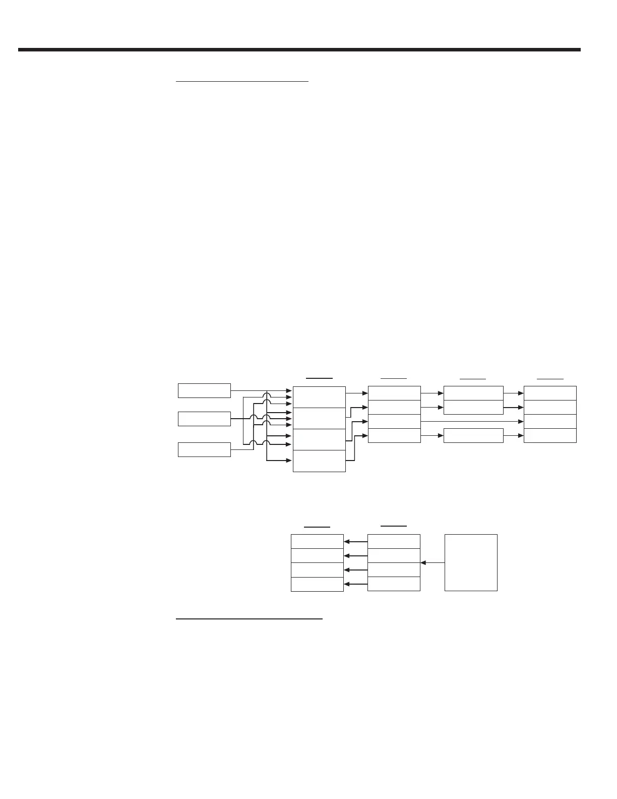
Process Data Overview
The basic serial interface on the keypad operator consists of four containers
for incoming data (PDI - Process Data In) and four containers for outgoing
data (PDO - Process Data Out).
Depending on the DIN66019II service used, the string of PDI data from the
telegram will be deposited into two or more of the containers. The containers
are then mapped (FB17-20) to a dened function (eg. Control Word, Speed,
Pretorque, Absolute Target Position) with the function structure also dened.
Depending on the function, the raw PDI data (FB34-37) may be scaled or
masked (FB05-07) before being processed by the drive (FB01-04).
The PDO data will originate from the DG parameters in the operator (viewable
from Combivis). This data will be mapped (FB13-16) to the four PDO containers
and then depending on the service, taken from the container and placed in
the response telegram (FB30-33).
PDI - Process Data Inputs
For the PDI, there are four fixed-functions established, each with a
corresponding structure denition: Control Word, Speed, Pretorque, and
Absolute Target Position.
Service 48
2 L
Service 50
1L 2W
Map Assignment
Map Assignment
Map Assignment
Map Assignment
Mask
Scale
Multiply, Right Shift (Divide)
Control Word
Speed Command
Pretorque Command
Target Position
Map Assignment
Map Assignment
Map Assignment
Map Assignment
PDO1
32 bit raw data
PDO2
32 bit raw data
PDO3
32 bit raw data
PDO4
32 bit raw data
DG Paramaters
Scale
Multiply, Right Shift (Divide)
Service 49
4 W
PDI1
32 bit raw data
PDI2
32 bit raw data
PDI3
32 bit raw data
PDI4
32 bit raw data
Fb34 - 37
Fb17 - 20
Fb05 - 09 Fb01 - 04
Fb30 - 33
Fb13 - 16
Process Data Inputs
Process Data Outputs

 Loading...


