59
Sin/Cos - Encoder Connections
5432 1
10 98 76
15 14 13 12 11
Sin/Cos
Drive connection X3A
Female SUBD 15 HD
Pin No. Signal Description
1 C-
Dierential signal to C+
2 D-
Dierential signal to D+
3 A-
Dierential signal to A+
4 B-
Dierential signal to B+
6 C+
SIN+ Absolute track for initial position and angular calculation
7 D+
COS+ Absolute track for initial position and angular calculation
8 A+
COS+ Incremental signals A for counter and direction detection
9 B+
SIN+ Incremental signals B for counter and direction detection
12 +5.25V
Power supply for encoder
13 COM
Reference potential for supply voltage
14 R-
Dierential signal to zero track R+
15 R+
Zero track
Encoder Card Part Number: Housing Size ≤ E 1MF5K8G-MZ56. Housing Size ≥ G 2MF5K8G-MZ26
• Max. Load capacity depending on Voltage Supply.
• Max. Load capacity at +5.0V; 300 mA. The specied current is reduced by the current taken from the sec-
ond encoder interface X3B interface (see Section 3.3.9).
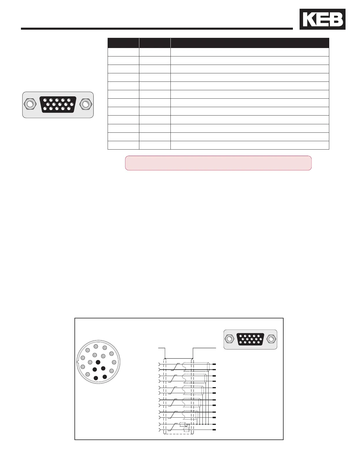
Connection of the encoder cable
Encoder interface X3A
Circular connector on
SIN/COS encoder
5432 1
10 98 76
15 14 13 12 11
8 A+
3 A-
9 B+
4 B-
6 C+
1 C-
7 D+
2 D-
15 R+
14 R-
13 COM
12 +5.25V
A+ 1
A- 2
B+ 11
B- 12
C+ 5
C- 6
D+ 14
D- 4
R+ 3
R- 13
COM 7
+5.25V 10
Pre-manufactured Sin/Cos cables offer the best solution against noise and disturbance while saving installation
time. The cables come in standard lengths of 5m, 10m, 15m, 20m, 25m and 30m. Specially designed cables
are available for applications 40m and up. The maximum length of KEB cable offered is 50m.
Cable Part Number
00S4209-00xx xx = length in meters, 10 = 10 meters
Mating Connector
0090912-004U for encoder (solder type)
Running in Conduit
When this cable must be pulled through metallic conduit, it is necessary to over size the conduit! Use of
a 1 1/2-inch trade size conduit will allow the connectors to pass without removal of the connectors. Cutting the
cable, or removal of the connectors or their housings voids the warranty and will result in problems with electrical
noise after the fact.
ONLY when the inverter is switched off and the voltage supply is discon-
nected may the feedback connectors be removed or connected!
1
2
3
4
5
6
7
8
9
10
11
12
13
14
15
16
17

 Loading...


