71
UVW - Encoder Connections
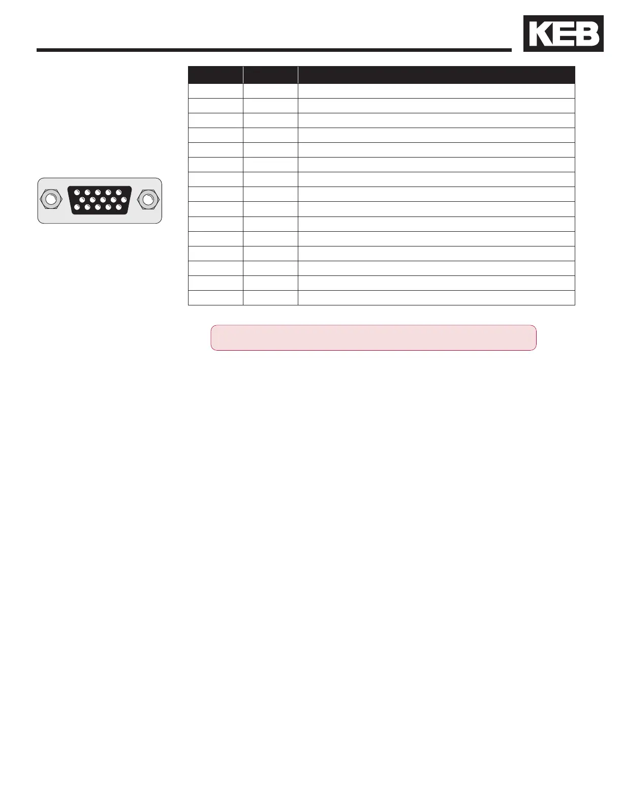
5432 1
10 98 76
15 14 13 12 11
UVW
Drive connection X3A
Female SUBD 15 HD
Pin No. Signal Description
1 A+
Incremental encoder input track A
2 A-
Dierential signal to A+
3 B+
Incremental encoder input track
4 B-
Dierential signal to B+
5 N+
Input zero track (not evaluated)
6 N-
Dierential signal to N+ (not evaluated)
7 U+
Block commutation track U
8 U-
Dierential signal to U+
9 V+
Block commutation track
10 V-
Dierential signal to V+
11 W+
Block commutation track
12 W-
Dierential signal to W+
13 5V
Voltage output 5V
14 COM
Reference potential for voltage supply
15 -
-
Encoder Card Part Number: Housing Size ≤ E, 1MF5K8G-ZZ08. Housing Size ≥ G 2MF5K8G-ZZ08
• Max. Load capacity depending on Voltage Supply
• Max. Load capacity at +5.2V = 400 mA. The specied current is reduced by the current taken from
the second encoder interface X3B interface (see Section 3.3.9).
Technical Data
• Input resistance: 120 Ohm
• Maximum input frequency: 200 kHz
• Encoder line number: 1...8192 inc
The following Sin/Cos encoders have been tested for use:
• Heidenhain ERN 423, 426
• Quantum Devices Q-Phase
However, this does not restrict the use of rotary encoder with the same
specications as other manufacturers.
ONLY when the inverter is switched off and the voltage supply is discon-
nected may the feedback connectors be removed or connected!

 Loading...


