Operation Manual ServoOne Supply Unit
19
ID no.: 1101.21B.6-00 Date:04/2020
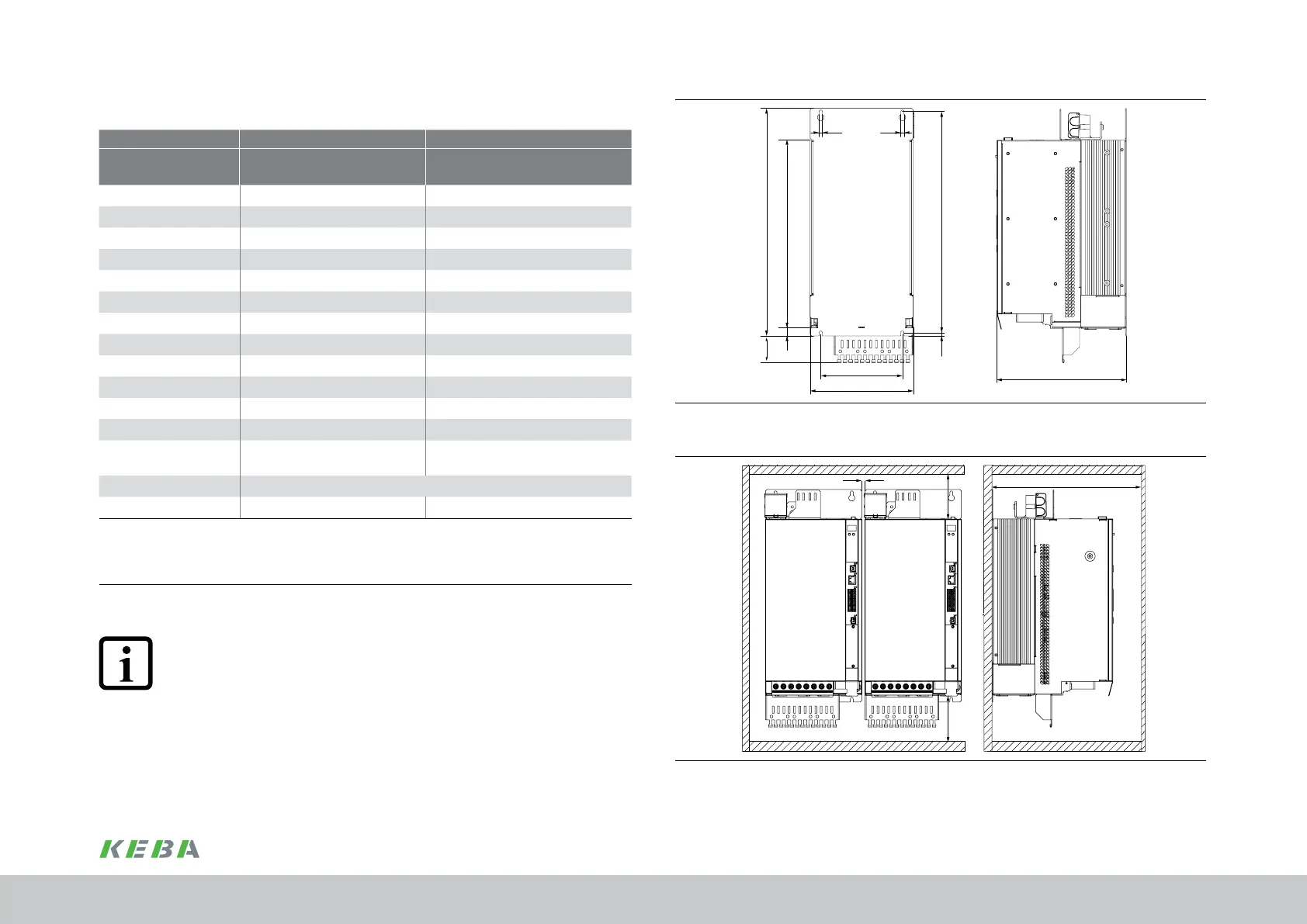
A
B
C1
H1
H3
H
H2
C
T
D D
Figure 3.6 Dimensional drawing wall mounting housing variant BG5 + BG6a (symbolic depic-
tion)
E
G
F
F
Figure 3.7 Mounting distance wall mounting housing variant BG5 + BG6a (symbolic depiction)
3.3.1 Dimensions, wall mounting housing variant
Size BG5 BG6a
Device
SO84.040.Sxxx.0
SO84.076.Sxxx.0
SO84.115.Sxxx.0
SO84.170.Sxxx.0
Weight [kg] 13 32
B (width) 190 280
H (height)
1)
345 540
T (depth)
1)
238 322
A 150 200
C 406.5 581
C1 6 10
H1 418.5 600
H2 15 20
H3 64 166
D 5.6 10
Fastening screws 4xM5 4xM8
E
Direct butt mounting, max.
2mm
Direct butt mounting, max. 2mm
/ 40
2)
F
3)
≥180
G
3)
≥300 ≥500
All dimensions in mm,
1) Without terminals, connectors
2) Mounting distance BG6a to other BG6a
3) Also pay attention to the bending radius of the connection cables
Table 3.1 Dimensions, wall mounting housing variant
NOTE:
On butt mounting devices with different drive powers you should arrange the
devices in descending order by power rating (e.g., viewed from the left, BG4-
BG3-BG2-BG1). This arrangement will minimise the thermal interaction. The
supply unit must always be tted beside the axis controller with the highest
power.
Mechanical installation
 Loading...

