Operation Manual ServoOne Supply Unit
26
ID no.: 1101.21B.6-00 Date:04/2020
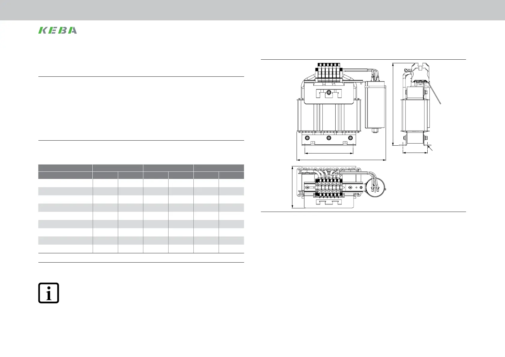
A1
H
A
B
D1
T
Figure 3.18 Dimensional drawing, input choke, based on BG5 as an example
3.7 Mounting input choke with lm capacitor
1.
Arrange the components such that adequate air circulation is ensured for heat
dissipation. As the lm capacitor has a viscous lling, the input choke must be
installed with the lm capacitor upright.
Pay attention to the bending radius of the connection cables.
For dimensional drawings/hole spacing see Figure 3.18, Figure 3.19 and Table 3.4.
2.
Mount the input choke on the mounting rail.
The thread surface area will provide good contact. The contact area must be bare
metal to establish a good ground connection to the switch cabinet ground.
3.7.1 Dimensions
For size BG5 BG6a BG7
For device SO84.040 SO84.076 SO84.115 SO84.170 SO84.375 SO84.540
B (width) 289 289 342 348 297 357
H (height) 252 268 292 321 347 565
T (depth) 119 136 175 175 319 308
A 156 156 176 176 224 310
A1 63 80 95 95 145 146
D1 7x13 7x13 9x13 9x13 10x18 12x20
D2 - - - - 13 13
Mounting screws 4xM6 4xM6 4xM8 4xM8 4xM8 4xM8
Weight [kg] 10.5 14 20 22 45 71
All dimensions in mm and not including terminals/connectors
Table 3.4 Dimensions, input choke
NOTE:
The input choke is only intended for installation in a switch cabinet because
the filter is designed in degree of protection IP00 without protection against
touching.
Mechanical installation
 Loading...

