Operation Manual ServoOne Supply Unit
51
ID no.: 1101.21B.6-00 Date:04/2020
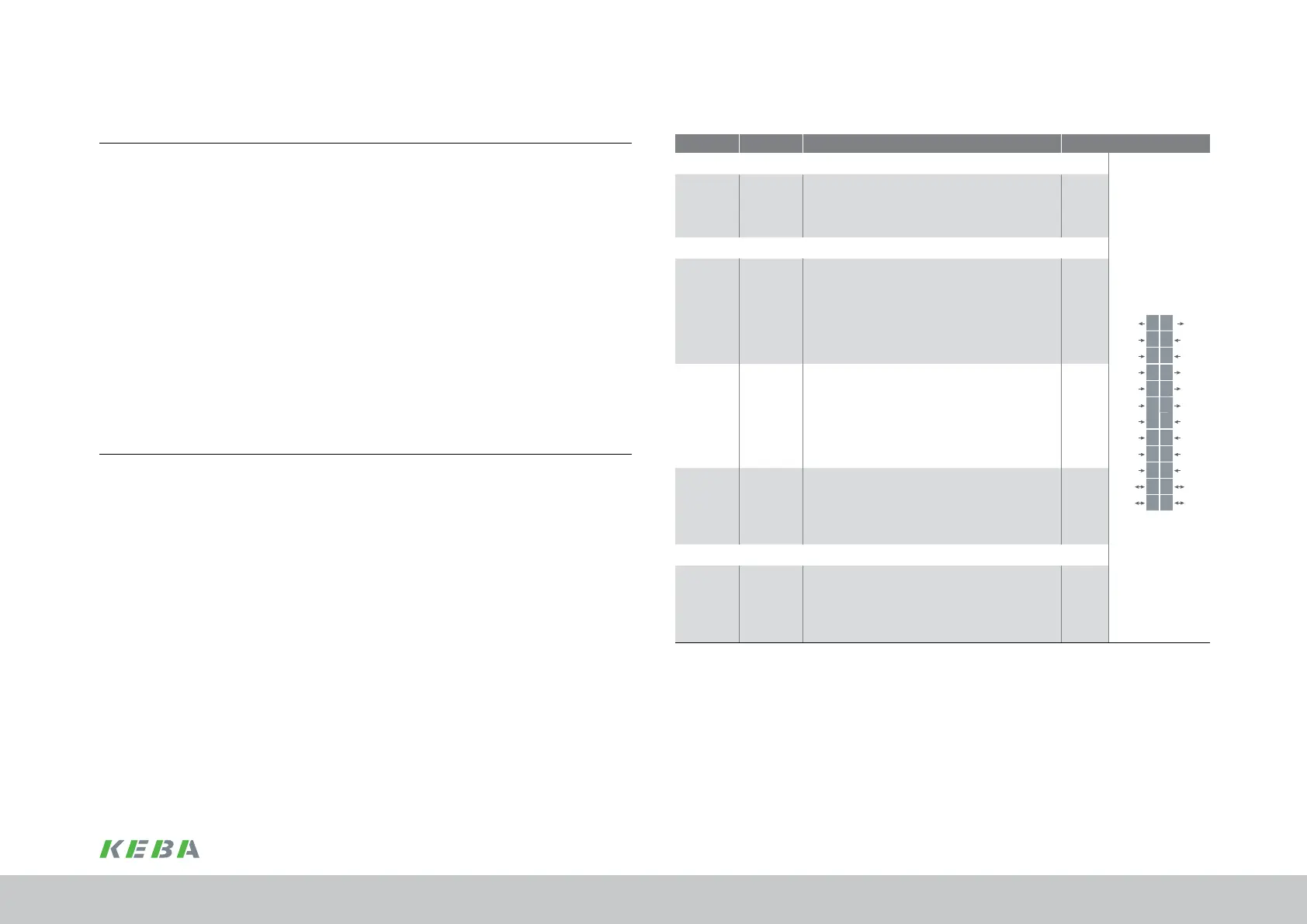
4.9.1 Specication, control connections
Des. Term. Specification Electrical isolation
Analogue inputs
REL
REL
ISDSH
ISD06
ISD05
ISD04
ISD03
ISD02
ISD01
ISD00
+24V
DGND
RSH
RSH
ENPO
OSD02
OSD01
OSD00
ISA1-
ISA1+
ISA0-
ISA0+
+24V
DGND
24
23
22
21
20
19
18
17
16
15
14
13
12
11
10
9
8
7
6
5
4
3
2
1
ISA0+
ISA0-
ISA1+
ISA1-
X4/3
X4/4
X4/5
X4/6
No function No
Digital inputs
ISD00
ISD01
ISD02
ISD03
ISD04
ISD05
ISDSH
X4/15
X4/16
X4/17
X4/18
X4/19
X4/20
X4/22
• Frequency range <500Hz
• Terminal scan cycle in = 1ms
• Switching level low/high: ≤4.8V / ≥18V
• At 24V typ. 3mA
Yes
ISD06 X4/21
• Frequency range ≤500Hz
• Switching level low/high: ≤4.8V / ≥18V
• I
max
at 24V = 10mA, R
IN
approx. 3kΩ
• Internal signal delay < 2μs suitable as
trigger input for quickly saving the actual
position
Yes
ENPO X4/10
• Frequency range <500Hz
• Response time approx. 10ms
• Switching level low/high: ≤4.8V / ≥18V
• At 24V typ. 3mA
Yes
Digital outputs
OSD00
OSD01
OSD02
X4/7
X4/8
X4/9
• Short circuit proof
• I
max
= 50mA, PLC-compatible
• Terminal scan cycle in = 1ms
• High-side driver
Yes
Table 4.10 Specication of the control connections
4.9 Control connections (X4)
1.
Check whether a complete device setup is already available, i.e. whether the drive
has already been congured.
2.
If so, a special control terminal assignment applies.
It is imperative you contact your project engineer to obtain the terminal assignment!
3.
Choose a terminal assignment.
4.
Wire the control terminals using shielded cables.
The following are imperative: 24VDC to X4/22 and ENPO X4/10 as start signal.
Earth the cable shields over a large area at both ends.
Rigid conductor sizes: 0.2 to 1.5mm²
Flexible conductor sizes with ferrules: 0.2 to 1.5mm²
5.
Leave all contacts open
(inputs inactive).
6.
Check all connections again!
Continue with commissioning in chap. 5 on page 59.
Note the following points:
y Always wire the control terminals with shielded cables.
y Route mains, motor and signal, DC power supply and braking resistor cables
separated from one another. Maintain a distance of at least 200mm.
y A cable type with double copper braiding, with 60...70% coverage, must be
used for all shielded connections.
Electrical installation
 Loading...

