Operation Manual ServoOne Supply Unit
27
ID no.: 1101.21B.6-00 Date:04/2020
3.8 Mounting mains lter
1.
Arrange the components such that adequate air circulation and heat dissipation is
ensured.
Pay attention to the bending radius of the connection cables.
For dimensional drawings/hole spacing see Figure 3.20 and Table 3.5.
2.
Mount the mains lter on the backing plate.
The thread surface area will provide good contact. The contact area must be bare
metal.
3.8.1 Dimensions
For size BG5 BG6a BG7
For device SO84.040 SO84.076 SO84.115 SO84.170 SO84.375 SO84.540
Type
FFU
3x56 K
FFU
3x80 K
FFU
3x130 K
FFU
3x180 K
FN 3359-
400-99
FN 3359-
600-99
B (width) 85 80 90 130 260 260
H (height) 250 270 270 380 300 300
T (depth) 90 135 150 180 115 135
A 60 60 65 102 235 235
C 235 225 255 365 120 120
G Ø 5.4 6.5 6.5 6.5 12 12
Mounting screws M5 M6 M6 M6 M10 M10
Weight [kg] 1.9 2.6 4.2 6.0 10.5 11
All dimensions in mm and not including terminals/connectors
Table 3.5 Dimensions, mains lter
NOTE:
The mains filter is only intended for installation in a switch cabinet because
the filter is designed in degree of protection IP00 without protection against
touching.
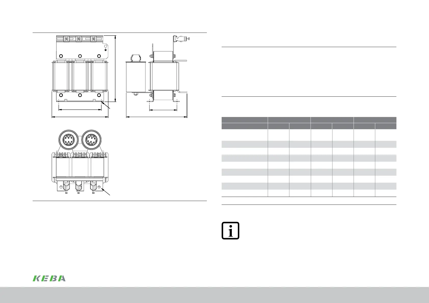
A1
H
A
B
ØD1
T
Figure 3.19 Dimensional drawing, input choke, based on BG7 as an example (SO84.375)
Mechanical installation
 Loading...

