Operation Manual ServoOne Supply Unit
22
ID no.: 1101.21B.6-00 Date:04/2020
H3
A
B
A1
C1
A2
S
D1
T
T1
H1
H4
H
D
D
H2
C
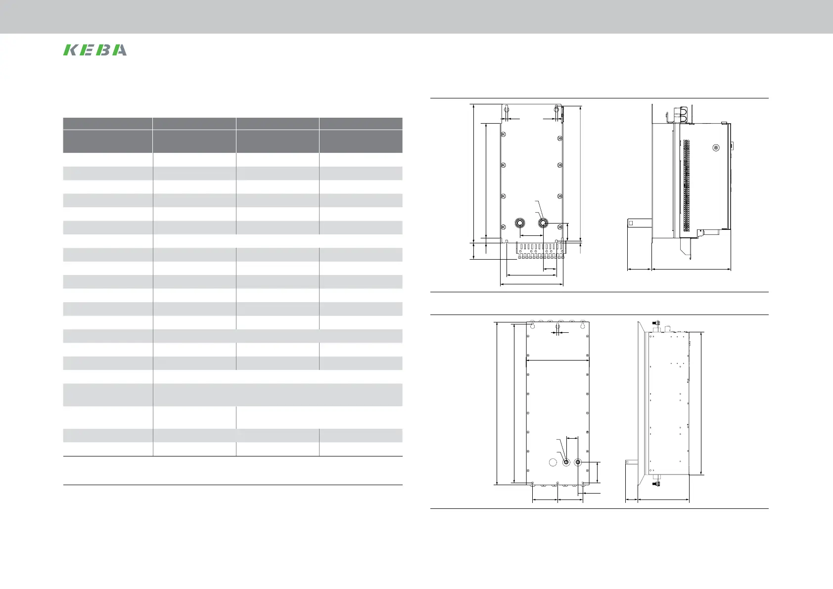
Figure 3.11 Dimensional drawing, liquid cooling housing variant BG5 + BG6a (symb. depiction)
H1 C
AA
T
B
T1
H
A1
A2
H3
S
D1
D
Figure 3.12 Dimensional drawing, liquid cooling housing variant, based on BG7 as an example
3.4.1 Dimensions, liquid cooling housing variant
Size BG5 BG6a BG7
Device
SO84.040.Sxxx.8
SO84.076.Sxxx.8
SO84.115.Sxxx.8
SO84.170.Sxxx.8
SO84.375.Sxxx.8
SO84.540.Sxxx.8
Weight [kg] 13 32 90
B (width) 190 280 380
H (height)
1)
345 540 855
T (depth)
1)
238 285 287
A 150 200 150
A1 40 65 29
A2 70
C 406.5 581 955
C1 6 10 14
H1 418.5 600 979/ 995
4)
H2 15 20 62
H3 54 57 124
H4 64 166 -
T1 74
D 6.5 10 12
Mounting screws 4xM6 4xM8 6xM10
S Female thread 3/8 inch (female thread)
D1 48 (bore for pipe tting)
E
2)
Direct butt mounting
Butt mounting ≥ 9 mm
(≥ 40 mm distance see Figure 3.10)
F
2) 3)
≥180
G
2) 3)
≥ 300 ≥ 500 ≥ 500
All dimensions in mm
1) Without terminals/connectors
2) See Figure 3.13, Figure 3.14
3) Also pay attention to the bending radius of the connection
cables
4) Without/with busbars
Table 3.2 Dimensions, liquid cooling housing variant
Mechanical installation
 Loading...

