Operation Manual ServoOne Supply Unit
49
ID no.: 1101.21B.6-00 Date:04/2020
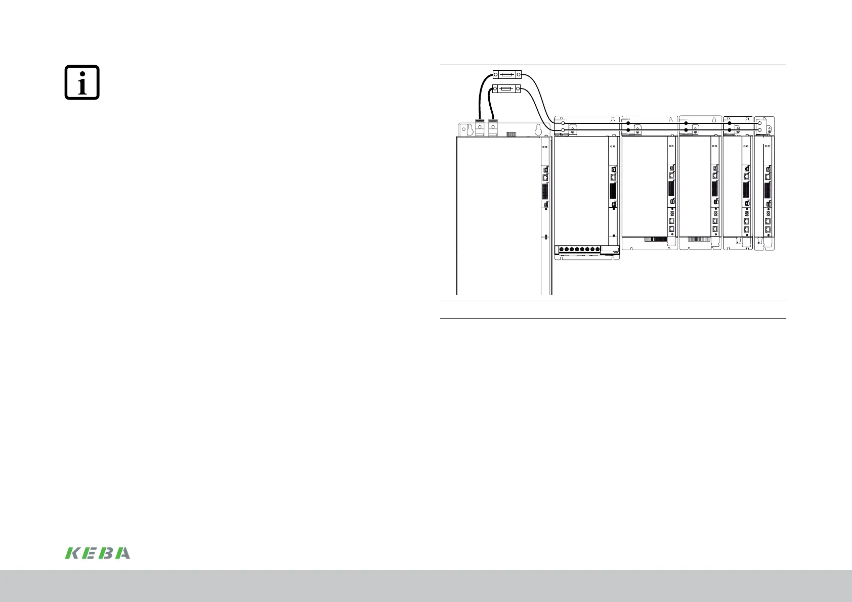
ServoOne DC BG 1
ServoOne DC BG 2
ServoOne DC BG 3
ServoOne DC BG 4
ServoOne DC BG 5
ServoOne
Supply unit BG 6a
+ +
–
+
–
+
–
+
F2
X11 X11
+
–
X11 X11 X11
X11
F2=DCfusesmax.160A/min.900VDC,utilisationclassgPV,gR,gRL,(gS)
Figure 4.22 Schematic: connection, DC power supply, BG6a to smaller DC axis controllers
NOTE:
You will find the permissible connection cross-sections and tightening torques
in chap.A.3
4.8.2 Connection, DC power supply BG6a and BG7
Connect the DC link terminals ZK+ and ZK- on the supply unit BG6a or BG7 to the
corresponding terminal on the next DC axis controller in the row.
Use suitable, in-house assembled DC connection cables for this purpose. The cables
must be short circuit proof and should be laid bundled in parallel; preferably use a
shielding sleeve for the shielding. The length of 2 m should not be exceeded.
Dene the cable cross-section to suit the application, however use as a minimum
50mm
2
CU. Pay attention to the local situation and conditions.
During the dimensioning of the DC connection cables, please take into account that the
DC currents can be up to 1.4-times the mains side input current. Given corresponding
design, cable protection for the DC connection cables can be provided by the mains
fuses F1.
If the design of the DC connection cables is different (e.g. reduction of the cable cross-
section), the cables must be protected by means of additional DC link fuses (see F2 in
Figure 4.22).
The DC link fuses are to be dimensioned to suit the current load and the cross-sections
selected and must be suitable for 900 V DC. Use utilisation class gPV, gR, gRL or gS.
For typical examples, see following pages Figure 4.23 to Figure 4.26 . For information
on further combinations, please contact your project engineer or our helpline, see “1.10
Service & Helpline”.
Electrical installation
 Loading...

